BiDiB is designed to control model railways, as there are control of locos, accessories and safe transmission from feedback information out of the layout to a connected PC. BiDiB is short for Bidirectional Bus and has the following advantages:
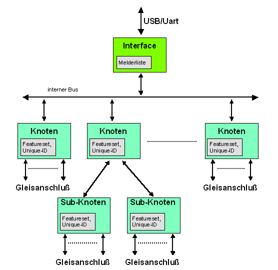
The above picture shows a typical arrangement. The protocol is suitable for different feedback systems and can manage simple home layouts up to large exhibition layouts. The Protocol can be easily adapted to nearly all requirements. For this purpose, there is a mandatory set of query and setting parameters existing that must be implemented in every feedback system. The following used terms will be summarized and explaned in the glossary.
Lenz and Tams introduced BiDi feedback systems by 2009, therefore the use of bi-directional data transfer between DCC decoders and control units was theoretically possible. Suitable feedback systems has been announced, but by the end of 2010, only the simple Tams RC Talk was available in the market. From the discussion about a future proof successor, the BiDiB protocol was created. This was the base for an enhanced draft, which also includes command stations, accessories and control panels.
At this point, I would like to say "Thank you" to my discussion partners, Mr. Tams, Mr. Bluecher and Mr. Herzog for their constructive input.
BiDiB® is maintained and developed further by a working group (BiDiB-Implement-Group). Among other, the sirs Kersten Tams, Markus Herzog and Wolfgang Kufer are authoritative members of this group.
Legal: This specification is provided "as is" and without any warranty of any kind, expressed or implied. Without limitation, there is no warranty of non-infringement, no warranty of merchantability, and no warranty of fitness for a particular purpose. all warranties are expressly disclaimed. The user assumes the full risk of using this specification. In no event shall any member of BiDiB-Implement-Group be liable for any actual, direct, indirect, punitive, or consequential damages arising from such use, even if advised of the possibility of such damages.
BiDiB is intended for use with model railroad control software and may be implemented without license costs at the PC side as well as on the hardware side. To ensure compatibility, the following license terms & conditions have to be observed:
This document describes revision 1.29 of BiDiB, updated June 21, 2023.
This document describes the basic message structure. Messages that are specifically associated with an application (e.g. switching, detection, driving,...) will be described in other documents or chapters.
| 1.29 | 2023-07-21 | added:
|
| 1.28 | 2020-05-31 | protocol version 0.6⇒0.8: streaming for features and accessories. added: extensions for DCC commands (F29…F68, DCC-SDF, analog command), preparations for automatic logon with DCCA, query of active locos, load type configuration for ports, global address detection, transport of debug outputs, explanation on local messages |
| 1.27 | 2017-04-07 | added: position reports, BiDiB system time, porttype SWITCHPAIR, configuration fingerprints, accessory emergency stop, accessory details |
| 1.26 | 2016-08-15 | added: BIDIB_ACCESSORY_PARA_STARTUP, BIDIB_ACCESSORY_PARA_OPMODE. Rework of all parts, explanations and clarifications. |
| 2016-02-25 | revised port control, added MSG_LC_PORT_QUERY_ALL, protocol version 0.6⇒0.7 | |
| 1.25 | 2015-11-28 | revised byte order of port addresses in the flat model |
| 1.24 | 2015-03-22 | added MSG_CONFIGX_GET_ALL, flat port model (see port control), protocol version 0.5⇒0.6 |
| 2014-12-04 | added new macro command FLAG_QUERY0 | |
| 1.23 | 2014-11-11 | add new configuration messages for ports (CONFIGX*) |
| 2014-08-14 | additional defines for POM (DCC generation) | |
| 2014-07-25 | additional items in the licence section | |
| V1.22 | 2014-06-26 | added: BIDIB_MSYS_SERVOMOVE_QUERY, longer responses for version queries |
| V1.22 | 2014-02-07 | added: MSG_ACCESSORY_NOTIFY, MSG_BM_DYN_STATE, MSG_CS_PROG, MSG_CS_PROG_STATE |
| V1.21 | 2013-12-16 | added: MSG_STRING_GET, _SET, MSG_STRING, FEATURE_STRING_SIZE |
| V1.20 | 2013-11-18 | added hints and explanation for turntables; BIDIB_CS_STATE_GO_IGN_WD |
| V1.20 | 2013-10-29 | added MSG_SYS_GET_UNIQUE_ID mandatory for standalone bootloader |
| V1.19.1 | 2013-10-21 | Translation from speed to DCC28/DCC14 now mandatory, formula and example added |
| V1.19 | 2013-10-04 | MSG_LC_OUTPUT_QUERY added; new features: FEATURE_RELEVANT_PID_BITS, FEATURE_CTRL_PORT_QUERY_AVAILABLE new: BIDIB_MSYS_ACC_OKAY_QIN1, BIDIB_MSYS_ACC_OKAY_QIN0, BIDIB_MSYS_ACC_OKAY_NF |
| V1.18 | 2013-07-18 | Additional responses to GET_SYS_MAGIC (Support for tiny bootloader). Added SecureSwitch definition to accessory |
| 2013-06-29 | Update of licence conditions | |
| V1.17 | 2013-06-18 | Introduction of a watchdog for DCC generation, added FEATURE_GEN_WATCHDOG |
| V1.16 | 2013-06-02 | more details on MSG_SYS_RESET, added FEATURE_CTRL_STRETCH_DIMM |
| V1.15 | 2013-04-20 | added transmission of error codes for accessory |
| V1.14 | 2013-04-02 | unified definition of switch time |
| V1.13 | 2013-03-25 | MSG_LOCAL_LOGON_REJECTED added. Error handling in case of too much participants |
| V1.12 | 2013-02-23 | MSG_BOOST_CURRENT will be replaced with MSG_BOOST_DIAGNOSTIC. |
| V1.11 | 2013-01-30 | Parameter added for MSG_BOOST_ON and _OFF |
| V1.10 | 2013-01-23 | MSG_CS_BIN_STATE completed |
| V1.09 | 2013-01-17 | FEATURE_BST_INHIBIT_AUTOSTART completed |
| V1.09 | 2012-12-21 | Explanations for MSG_CS_DRIVE_ACK; MSG_BOOST_QUERY completed |
| V1.08 | 2012-11-13 | Explanation and final coding for MSG_BM_SPEED, FEATURE_BM_ISTSPEED_INTERVAL |
| V1.07 | 2012-10-12 | Supplementation of the class accessory, Parameter at MSG_STALL; Explanation for MSG_CS_DRIVE |
| V1.06 | 2012-09-26 | Accessory class: MSG_LC_WAIT added, Spelling corrections. |
| V1.05 | 2012-09-24 | Occupancy class: Additional commands MSG_BM_GET_CONFIDENCE and MSG_BM_CONFIDENCE. |
| V1.04 | 2012-07-25 | Additional explanations for MSG_VENDOR*. MSG_SYS_PING / MSG_SYS_PONG got a new parameterp Supplementation for switch class: BIDIB_MACRO_RESTORE, BIDIB_MSYS_DELAY_RANDOM, MACRO_PARA now 32 Bit. |
| V1.03 | 2012-07-25 | Additional explanations for MSG_VENDOR*. |
| V1.02 | 2012-06-06 | Explanation for MSG_NODE_LOST corrected. |
| V1.01 | 2012-03-19 | MSG_FEATURE_GETALL, MSG_FEATURE_GETNEXT, MSG_NODETAB_GETALL, MSG_NODETAB_GETNEXT, Transmission process for Features und Nodes explained. |
| V0.13 | 2012-02-21 | MSG_BM_ADDRESS with opportunity to report multiple occupancy. reference at MSG_BM_SPEED. |
| V0.12 | 2011-07-20 | Local command for PING and PONG added; MSG_BM_MIRROR_OCC and _FREE added. |
| V0.11 | 2011-07-20 | New feature-parameter for Booster, system time, MSG_BOOST_STAT messages extended. Current setting for booster added. |
| V0.10 | 2011-04-02 | Suggestions for decoder registration added, new message MSG_BM_BLOCK_CV for block reading of CVs.. |
| V0.09 | 2011-02-24 | Changes at the NODE_TAB (in case of no sub-nodes), more failure codes added. MSG_SYS_GET_ERROR added. |
| V0.08 | 2010-12-20 | Booster class completed. |
| V0.07 | 2010-12-07 | Explanations for Vendor config, V_VALUE added; failure messages extended; MSG_SYS_MAGIC with index 0;
Enable /Disable with auto-forward to sub-nodes. BM_MSG for accessory added. MSG_SYS_IDENTIFY_STATE added. |
| V0.06 | 2010-12-06 | Explanations for NODE_CHANGE added |
| V0.05 | 2010-12-01 | Unique-ID explained, PKT_CAPACITY new added, ClassID added |
| V0.04 | 2010-11-29 | Packet structure for routing optimized, Fine tuning. new added: MSG_BM_SET_SIZE, MSG_BM_GET_SIZE |
| V0.03 | 2010-11-25 | Extension for hubs and sub-nodes. |
| V0.02 | 2010-11-17 | Extension for heterogeneous feedback modules, Individualisation of feature sets for single modules |
| V0.01 | 2010-11-03 | Initial document |
BiDiB is designed as a stateless protocol. There exist several safeguards to deal with message losses.
The most important property to achieve a high error tolerance is the idempotence of the messages. Generally messages transmit states, not commands or orders. Their reception is typically acknowledged by the node with a message of equal content. Thereby the transmission can simply be repeated in case of an error, without causing undesired actions when received multiple times. This holds in particular for the critical model railroad applications driving, controlling and feedback. An identifier is always used in sequential transmissions with multiple messages, so that missing information can be requested again.
Communication errors on the other hand are reported once only and not repeated, which simplifies the implementation. A loss of an error message can be handled the same way as the absence of the regular answer. If multiple errors occur together, they can be put in a queue to be retrieved, but they don't have to be repeated either. If an error persists, it simply is reported again at the next attempt of using the object. A recovery from an error is generally not reported. Some objects where fault/error conditions are intrinsic (e.g. boosters and accessories) constitute exceptions hereof, retention or repetition might be required for them.
Likewise dealt with are spontaneous events that are not mission-critical. The loss of such messages can only be detected by checking sequence numbers, but there is no mandated error handling and no way to retransmit the message. For operation critical events (Occupancy, Accessory) there are acknowledgement mechanisms "Secure-ACK" and "Secure-Switch" as safeguards.
The continuing revolution of BiDiB is deep-seated in the protocol. Rigorous attention is paid to backward compatibility of new revisions of the specification. Extensions to the functional range are usually readily possible, as they are typically optional and can be ignored. In case of backward incompatible changes the protocol version is incremented, which can be retrieved from every node. This does allow the support of out-dated implementations and even assures the compatibility with unknown functions to some degree.
The following terms for each protocol participant or properties will be used in this document:
| BiDiB: | The protocol standard, the way how messages are encoded. |
| BiDiBus: | One possible physical implementation, specially for wired connections within a model railway. BiDiBus is based on RS485 and uses RJ45 cables. |
| Bus system: | The complete setup, consisting interface and nodes (i.e. detectors) + possibly internal connections. |
| Class: | Nodes are divided in classes, depending on their basic properties. There are as example: occupancy detectors, DCC Generators, Switch outputs, Track panels. |
| Detector: | A single node within the BiDiB system which is able to detect track occupancy and recognize BiDi feedback signals. |
| Feature: | Particular property of a node (e.g. 'detector can recognize loco direction'). Features can be queried and configured individually. |
| Host: | The control computer, usually a standard PC with appropriate software. |
| Hub: | A node in one level of the bus system, which is also an interface to the next lower level. |
| Interface: | The location within a level (structure) in the bus system, which communicates with the host or parent-node. |
| Logon: | The attempt of a node to get a logical connection to an interface. The logon is acknowledged and the host is notified about the change. |
| Node: | A subscriber inside the BiDiB system (occasionally distributed) hardware. A subscriber within a level might be also an interface for the next sub-level (Hub-functionality). |
| Unique-ID: | The globally biunique node identifier. It contains the announced classes, the manufacturer code, and a vendor-specific number derived from the hardware ID. |
| Node-address: | The automatic assigned number from the interface (byte), under which the node is (at this level) addressed in this session. (NODE_ADDR) |
| Magic: | A (meaningless) number, which will be queried by the host during interface startup. For example the correct baud setting can be recognized. (=system id) |
An system addressed with BiDiB is organized like folders: The host provides an interface that allows it to establish a communications link and the interface allows him access to a (flat) array of nodes. Each of these nodes is usually a component that contains a particular function (for example, a detector with feedback contacts). But it is also possible that this block itself is an interface too, which holds a further structure (like subfolders). This achieves high flexibility in wiring possibilities and also in the heterogeneity of the connected detectors.
BiDiB is able to assign addresses automatically to nodes. Each node has an unique manufacturer-programmed number that is part of the Unique-ID. During startup of the feedback system, the interface searches existing nodes within its structure and assign a local address to each node. This address has the length of one byte. The interface builds a assignment table with all available nodes, their Unique-ID and their local address. Nodes itself can be also interfaces which gives a threaded structure. The maximum address length within the thread is 4 bytes.
This assignment table is different on each startup and will be automatically extended if a new node is added to the bus. In this case, the interface transmits a message to the host.
Internal to the host, the nodes are also stored with their unique ID, besides the program-specific things like screen position and node name. The host will retrieve the mapping from the interface during startup and gets the valid local addresses for this session that belongs to the unique IDs. The mapping between the object on the user interface and the model hardware is done through the node identity and is therefore independent from the current address assignment.
To facilitate the replacement of nodes, it should be minded in host programs that the Uniqued-ID assigned to a node object can easily be exchanged for another one. Because the unique ID of a device cannot be set by the user, they cannot program the replacement node to the "old address" to continue using the mapping configured in the program; instead it is necessary to make the change within the host software. The swapping of the unique ID is needed for instance when replacing a defective device by a identically constructed one, when upgrading hardware to a superior product with more outputs, or when deploying a different product firmware for more functionality.
BiDiB protocol is suitable for different transmission media such as serial connection, USB, RS485, Ethernet or wireless (with an adapted framing for each media). For specifications, refer to the respective documents.
The respective physical layer ensures the correct framing and bytewise, transparent transport of BiDiB message packets. The transfer layer must secure the transport of the data with CRC. The transfer layer must at least be able to transport messages with a size of 64 bytes.
CRC means the CRC8-Byte; On the transmitter side, the polynom x8 + x5 + x4 + 1 will be generated over the message, starting at the first byte from the message, Init=0, none inverted. On receiver side, the CRC with the same polynom will be generated over the whole message including CRC. The result must be 0.
A MESSAGE is structured as follows:
MESSAGE ::= MSG_LENGTH  MSG_ADDR  MSG_NUM  MSG_TYPE  DATA
MSG_LENGTH ::= 0x00 | … | 0x7f
MSG_ADDR ::= MSG_ADDR_STACK  0x00
MSG_ADDR_STACK ::= ε | NODE_ADDR  MSG_ADDR_STACK
NODE_ADDR ::= 0x01 | … | 0xff
MSG_NUM ::= 0x00 | … | 0xff
MSG_TYPE ::= 0x00 | … | 0xff
DATA ::= ε | ANY_BYTE  DATA
ANY_BYTE ::= 0x00 | … | 0xff
A message contains the length, an address specification, a (consecutive) message number, a type specification and optional parameters. These fields are described below:
| 0x00 | Offset for downlink messages |
| 0x80 | Offset for uplink messages |
| 0x00 | Offset for system messages |
| 0x10 | Offset for feature and user messages |
| 0x20 | Offset for feedback detector messages |
| 0x30 | Offset for booster messages |
| 0x38 | Offset for accessory, switch and macro messages |
| 0x60 | Offset for DCC generator messages |
| 0x70 | Offset for local messages (with special rules, see below) |
The data securing against transmission errors is the responsibility of the respective transport medium (e.g. CRC in case of serial transmission). The protocol itself doesn't provide message retransmit, critical messages are secured at a higher level (e.g. with Secure-ACK or corresponding response of the node).
The message length (MSG_LENGTH) does not only delimit messages where multiple are sequenced back-to-back, but also specifies how many DATA bytes are actually available as message parameters. This might indeed be more or less bytes than the message type suggests. Thereby optional parameters can be accomplished that are set to default values if not existent. If less parameters are sent than necessary, the node responds with an error message. If more parameters are sent than expected, the surplus bytes are ignored; this assures forward compatibility.
A message may have a length up to 64 bytes (MSG_LENGTH=63), all transport layers need to support these. Longer downstream messages can, as long as supported by the respective transport layer and node, be allowed per node via the MSG_PKT_CAPACITY message. To send a long message to a node, all interfaces on the transport path have to support this as well. Longer upstream messages shall be limited in accordance with the lengths used in the downstream.
BiDiB allows to wire subnets and connect them in star topology via hubs (similar to USB). This provides scalability for large model layouts. For smaller layouts, probably only one network will be build and therefore the information in this chapter can be skipped for now.
Local address assignment in sub-networks is described in a further document For the protocol description, only the results of this process are relevant.
A maximum of 4 cascaded networks is allowed. This limitation is intended to facilitate host implementations, thereby the respective current local address of a endnode is limited to 32 bits.
The following rules apply for the routing of messages:
To enable the parent node, respectively the host, to detect this structure, appropriate commands are existing:
If there is a change in the assignment table during operation (e.g. connect or disconnect), the interface sends a MSG_NODE_LOST or MSG_NODE_NEW message anyway. This message must be acknowledged by MSG_NODE_CHANGED_ACK (or a complete node table query). Both messages MSG_NODE_LOST, MSG_NODE_NEW and also MSG_NODE_CHANGED_ACK have the (continuous) version number of the table as a parameter. This ensures that all changes at the bus structure will be recognized.
Changes in the node table should be avoided by the interface (e.g. transmit no logon request). If there is a change in the node table while being queried and transmitted with MSG_NODETAB_GETNEXT, the interface must start over again with the transmission of a new MSG_NODETAB_COUNT (but with an incremented version number).
Each node has a distinct identifer, this number is called Unique-ID. The Unique-ID contains 7 bytes:
| 1. Byte | ClassID
This is a bit field indicating the class membership of this node. A node may also belong to several classes at once. The classes serve as a quick reference for the host about which functionalities can be found on this specific node. To rapidly locate a feature-based subfunctionality it is enough to only query the nodes which have set the corresponding class bit. If a node has implemented commands of a particular class, the appropriate class bit must be set as well. Conversely, it must know the commands of the announced classes and answer them correctly. Even if in the current configuration no objects are available, it should register the class and yield 0 for the count.
Reserved bits must be coded as 0. | ||||||||||||||||
|---|---|---|---|---|---|---|---|---|---|---|---|---|---|---|---|---|---|
| 2. Byte | ClassID Extension; this byte is reserved and must be coded with 0. | ||||||||||||||||
| 3. Byte | Vendor-ID: The same coding as DCC is used here, see NMRA Manufacturer ID Numbers. | ||||||||||||||||
| 4.-7. Byte | Product ID, comprising of 32 Bit.
These 4 bytes (= 32 bits) are split into a product identifier (lower 'p' bits) and a serial number (upper 's' bits). This allows for an easier identification of nodes by analysis tools and host programs. The coding in BiDiB is always little-endian (low-byte first), the product identifier starts at bit 0, first byte. It is up to the vendor, how many bits he uses for product and for serial number. However, a default of 16 bit / 16 bit is recommended. The feature FEATURE_RELEVANT_PID_BITS defines, how many bits are used for product ('p'). If the feature FEATURE_RELEVANT_PID_BITS doesn't exist, the default of 16 bits / 16 bits is used. |
The uniqueness of the product ID (and with it, the Unique-ID) is guaranteed by every vendor through the hardcoded serial numbers. Neither the unique ID nor the product ID constitute a fixed hardware identifier however, one and the same device can have several firmwares installed which may differ in their classes or even product types. Only the serial number remains the same normally, but on its own that is not necessarily unique.
Additionally, there might be a user string stored in the node (nick name, see MSG_STRING). This name can be used as alternative for the presentation of the node.
Connecting to a BiDiB system can be done according to the following list:
Nodes declare different classes via their Unique ID, e.g. occupancy detection, hub or booster functionality. To what extent a class is implemented is announced through feature settings.
For each class there are mandatory messages that have to be implemented, as well as optional messages that are only available if a feature declares them to be.
A BiDiB system has a global system time available to achieve a higher accuracy in time-based measurements. Various messages may contain a timestamp for the respective event, this allows for better results in vehicle tracking and calibration. The uncertainty in the latency of the data transmission is eliminated.
The BiDiB system time has a resolution of 1 millisecond and is represented by a 16-bit integer with cyclic overflow An error margin of ±5 ms between the clocks of all nodes in a system is aspired.
To facilitate a time measurement across different nodes, the clocks of the nodes have to be synced. This synchronisation happens on every bus level depending on the transport layer and is carried out by the respective interface. Whether an interface/hub does or not support it must be stated in the product description.
The synchronisation typically happens through a periodically emitted broadcast message with a timestamp. On the receipt of this message, the local node clock is set to the system time. Delays on the communication path or internally at the transmission and reception need to be considered and have to be corrected through according offsets, the arising inaccuracy should be ±1ms per bus level at most. With this approach a (small) step in the time series at the point of adjustment may occur, a host will need to take such into account.
If the synchronisation is absent, a node must refrain from the use of timestamps as soon as the resulting uncertainty becomes larger than ±3 ms. Example: if a processor clock rate has a divergence of up to 10ppm (0,01 ‰), then it should not use its local clock from about 100 s after the last synchronisation.
An interface should wait for synchronisation from the upper level before supplying the system time to its subnodes. If a synchronisation message fails to appear until the SYS_ENABLE (or a reasonable timeout), the interface may use its local clock time and synchronise the bus structure on its own.
The messages, which are used on the BiDiB system, can be divided into the following categories:
| System | Software and hardware version and product identification query, system start and -stop, connection settings, node address settings and queries. |
|---|---|
| Feature | Querying and setting of the node properties (features). |
| User-Config | Open messages for advanced, vendor-specific configuration. |
| Messages for firmware updates | Uploading of new node software. |
| Messages for Detectors | Occupancy reports and decoder feedback |
| Messages for Booster | Monitoring of boosters |
| Messages for command stations | DCC motion and switch commands |
| Messages for accessory control | Turnouts, signals, track system functions |
| Messages for configuration and direct port control | Illumination, animations, sound, peripheral equipment |
| Local messages | Link establish, synchronisation, link control |
Downlink describes the direction Host -> BiDiB-System, uplink means the direction to the host.
In general, messages occur spontaneously at the uplink (after approval at the interface). Some messages types can be switched on or off by feature settings.
For local communication inside a specific bus level further messages may be used for link control, logon/logoff or time synchronisation.> Depending on the topology and used physical layer a different set of local messages may be required, governed by the respective transport layer specification.
The message type ranges 0x70 to 0x7F (downstream) and 0xF0 to 0xFF (upstream) are reserved for local messages. This allows the partitioning and separate handling of these messages on the link layer.
Local messages are categorically exempt from sequence numbering to not interfere with the index progression of the overarching connection between host and target node. They are transmitted with sequence number 0. On reception, it is not evaluated and the receive-counter is not modified.
System messages are mandatory for all standard BiDiB nodes, only exception are bootloader nodes, see MSG_SYS_MAGIC for more details.
Common system messages
The addressed BiDiB Node should transmit the system identifier. No other data will follow. This message shall be send prior any other request to the node.
The node responds with its SYS_MAGIC, which also codes the general behaviour of the node.
Query for the supported BiDiB protocol version. No other data will follow.
The corresponding node responds with the version of the protocol supported by its software.
No other data will follow. The node will be released, from now on, spontaneous messages are possible (e.g. change of occupancy states, new added hardware). The message is automatically passed to all other subnodes (inherited). No acknowledgement will follow.
The BiDiB system will be blocked, spontaneous messages are disabled at this point. Events which occur in the SYS_DISABLE state will not be cached, yet node states can be queried targeted. The message is automatically passed to all other subnodes (inherited) and should therefore be addressed only to node 0. No acknowledgement will follow.
Query for the Unique-ID and configuration fingerprint of a node. No other data will follow.
The corresponding node responds with MSG_SYS_UNIQUE_ID.
(The Unique-ID of a node is also stored in the node table of its interface).
Query of the node's installed software version(s). No other data will follow.
Followed by one byte.
The corresponding node in the BiDiB system is initiated to send an empty message (MSG_SYS_PONG) back. This response must be received within 250 ms, otherwise the host has to consider the corresponding node as failed. The passed parameter (byte) is returned by MSG_SYS_PONG.
No other data will follow.
The corresponding node in the BiDiB system is initiated to send a message of type MSG_LOCAL_PONG back. This response must be received within 250 ms, otherwise the host has to consider the corresponding node as failed and transmit this failure with MSG_NODE_LOST to the host.
(In case of BiDiBus, the token and the answer to that token takes over this function.)
Followed by one byte: Identify is switched off, 1: Identify is switched on.
The corresponding node in the BiDiB system is instructed to display a local identify indicator (e.g. a flashing LED). The node responds with a MSG_SYS_IDENTIFY_STATE message.
The last occurred (but not any spontaneous) error message is read. The error memory is cleared through reading. If there is no error, an empty error message (i.e. error number 0) is returned.
Followed by two bytes (TIMEL, TIMEH) with the BiDiB system time, TIME indicates the point in time of the last frame marker prior to the message. The node sets its local clock to the received timestamp, possible data transit times must to be compensated by corresponding offsets. The message is not replied to.
Example: A node receives MSG_LOCAL_SYNC 3. The duration from the frame signal to the processing of the message amounts to 2 ms. The internal clock will be set to 5.
System messages for bus management
Hints for implementation: this messages are mandatory, but these messages include only variable data at interface nodes. Simple nodes have constant data. This means the answers to MSG_NODETAB_GET* etc. can be stored as constants and can be implemented also on very small microcontrollers. BiDiB has an automatic node assignment (e.g. detector, booster, etc.). This mapping is stored in the interface and can be collected from there. For this purpose, the following messages are provided:
The BiDiB system will be reset with regard to the host interface and the allocation of all nodes is carried out again. The previous assignment table is void.
All message sequence numbers in the upstream will be set back to zero but the function of the node remains.
If this message is addressed to a node, it shall log off (ie. shutdown for 1s, the interface will drop the node) an try to reconnect again. Internal states of the node may be lost.
With this command, the interface is caused to transfer the current assignment table of Unique-ID and local address. This transfer is a series of messages, it is started with a MSG_NODETAB_COUNT and will be followed by MSG_NODETAB, each of which are triggered by MSG_NODETAB_GETNEXT.
While the transfer is in progress, new inquiries with MSG_NODETAB_GETALL lead to abortion and restart of the transfer.
If the table does not yet exist, the interface responds with a MSG_NODETAB_COUNT = 0 message. In this case, the host must ask for it again after a few ms.
If the table is existing, the interface responds with MSG_NODETAB_COUNT = 'table length'.
This command causes the interface to send the next line of the node table. No parameters follow.
The node responds with a MSG_NODETAB message. In case there is no (more) line on hand, it responds with MSG_NODE_NA 255 instead. If there was a change in the node table since the last transmission of MSG_NODETAB_COUNT, the node responds with MSG_NODETAB_COUNT and starts over with sending MSG_NODETAB messages (with the incremented version number).
With this command, it is possible to read in the maximum message length that a node can handle. This corresponds to the maximum length of a message sequence when it consists of only one message, and thereby the maximum number of bytes in a packet (between two frame markers).
The node responds with a MSG_PKT_CAPACITY message. Until a node responds with a value above 64, the default restriction to 64 is in effect.
Followed by one byte with the confirmed sequence number (version number of the node table) of NODE_NEW or NODE_LOST message. The host sends this message within 250ms to an interface when he received a notification for a lost or newly added node. If the interface gets the same version of node table that it has sent in the last change notification, this and all previous changes are considered as acknowledged.
Followed by one byte with the local address (NODE_ADDR) and 7 bytes with the Unique-ID. Only if the node has verified that the received Unique-ID and the internal Unique-ID is identical, he may set his local address to received NODE_ADDR.
This message will be sent as broadcast and with MNUM = 0. It is always interpreted, even if no login attempt was made. It is therefore possible to assign a local address to a node before the general logon.
Followed by 7 bytes with the Unique-ID. The logon attempts of the addressed node are refused.
Possible causes for the rejection of the LOGON can be:
Simultaneously with the MSG_LOCAL_LOGON_REJECTED, the interface sends an error message with BIDIB_ERR_BUS to the host.
System messages for layout management
(Hints for implementation: this messages are mandatory)
This command transmits a model time for layout appliances. This clock typically runs accelerated compared to the real time. Followed by 4 bytes (TCODE0, TCODE1, TCODE2, TCODE3) with the time value. The coding of these bytes is the same as the coding of the corresponding DCC command.
| Field | Encoding | Meaning |
|---|---|---|
| TCODE0 | 00mmmmmm | mmmmmm = Minute indication, value range 0…59. |
| TCODE1 | 100HHHHH | HHHHH = Hour indication, value range 0…23. |
| TCODE2 | 01000www | www = Weekday, 0=Monday, 1=Tuesday, ... 6=Sunday. |
| TCODE3 | 11ffffff | ffffff = Clock acceleration factor, ffffff=0 means clock is stopped. |
Every field consists of a 2-bit type and 6-bit value. The host sends the complete time package every model-minute.
Is the system is stopped, the clock factor 0 should be sent.
On bus implementations, this message should be preferably send as broadcast.
Common system messages
Transmission of the system identifier: This variable is used for identification and transmission control. Followed by 2 data bytes, MAGICL, MAGICH which indicates the system identifier. The system identifier is transmitted with a transmission sequence index 0, this restarts the synchronisation of message sequence at host side.
| MAGICL | MAGICH | Description |
|---|---|---|
| 0xFE | 0xAF | BIDIB_SYS_MAGIC = Regular BiDiB Node |
| 0x0D | 0xB0 | BIDIB_BOOT_MAGIC = reduced bootloader |
| … | … | reserved |
If a node responds to MSG_GET_SYS_MAGIC with BIDIB_BOOT_MAGIC (=0xB00D), this node has a very reduced functionality support only some commands (see table) and firmware update (bootloader). The node doesn't know any features and will not respond to feature queries. However, the feature FEATURE_FW_UPDATE_MODE (254) is equal 1 (although it isn't queriable). Also the fault detection and treatment is reduced in this node, but the check of the integrity of the data transmission (CRC) is still mandatory. The node hasn't set any ClassID bits.
| Downstream | Upstream |
|---|---|
| MSG_SYS_GET_MAGIC | MSG_SYS_MAGIC |
| MSG_SYS_GET_P_VERSION | MSG_SYS_P_VERSION |
| MSG_SYS_GET_SW_VERSION | MSG_SYS_SW_VERSION |
| MSG_SYS_IDENTIFY | MSG_SYS_IDENTIFY_STATE |
| MSG_FW_UPDATE_OP | MSG_FW_UPDATE_STAT |
| MSG_SYS_RESET | |
| MSG_LOCAL_LOGON_ACK | MSG_LOCAL_LOGON |
| MSG_SYS_GET_UNIQUE_ID | MSG_SYS_UNIQUE_ID |
Followed by one byte. This message is a response to the MSG_SYS_PING request, while the transferred byte in PING will be sent back.
Empty message, no other data will follow. This message is the response to MSG_LOCAL_PING.
Transmission of the supported protocol version. Followed by 2 data bytes which encode the BiDiB protocol version.
| Parameter | Description |
|---|---|
| P_VERSIONL | Minor protocol version number |
| P_VERSIONH | Major protocol version number |
The node sends its unique identifier. Followed by 7 bytes with the Unique-ID and optionally 4 bytes with a configuration fingerprint.
The fingerprint is a 32 bit checksum applied to all settings of the node. Those include:
Explicitly exempt are all bus and operation states (even those that are persisted across power cycles), supported protocol versions and firmware revisions (assuming nothing else changes).
The fingerprint is computed by the node using a good (uniformly distributed, chaotic, efficient) but not necessarily cryptographic hash function. When a configuration value changes, the fingerprint changes as well.
Transmission of the software version: Followed by 1 to 16 triples (3 bytes each), vendor specific. Inside each triple the sub revision index is transmitted first, the main revision index is transferred last. Newer versions have a numerically larger version index.
The first triple denotes the software version of the node, additional triples may code the version of subsystems (like coprocessors, hardware).
Note: up to BiDiB specification revision 1.21 only one triple was defined as answer.
Followed by 1 byte with the identify status: 0: off, 1: on.
This message is sent when identification of the node was triggered, either by host command (MSG_SYS_IDENTIFY) or locally by the identification button.
Recommendation: If the identify button is assigned to more than one function (e.g. if a decoder can also be programmed via DCC address-learning), a short press should execute identify, a long press should execute the DCC learning mode. This recommendation ensures the same behaviour across different modules.
Error message of a node. The errors take place either by a query (by MSG_SYS_GET_ERROR) or spontaneous (if the node is enabled). Followed by one byte with the error type and occasionally other parameters. Depending on the error, the processing of the data will not be possible any more.
| Value | Name | Meaning | ||||||||||||||
|---|---|---|---|---|---|---|---|---|---|---|---|---|---|---|---|---|
| 0x00 | BIDIB_ERR_NONE | The node has no errors (any more) in the fault memory. | ||||||||||||||
| 0x01 | BIDIB_ERR_TXT | The node sends a text error message: followed by one byte with the length description, followed by ASCII-characters of the error message. | ||||||||||||||
| 0x02 | BIDIB_ERR_CRC | The received message (or the message packet) had a CRC error,
followed by one byte with the MSG_NUM of the faulty message.
The node discards the received message packet. Note: this error message is only useful on point-to-point links. On implementations with broadcasted messages, the receiver should not response with an error message (only discard the received data). | ||||||||||||||
| 0x03 | BIDIB_ERR_SIZE | The received message has too small length (too few parameters). Followed by one byte with the MSG_NUM. The node discards the received message. | ||||||||||||||
| 0x04 | BIDIB_ERR_SEQUENCE | The received message sequence has an sequence error, messages have been lost. Followed by one byte with the expected MSG_NUM (if there had been no sequence error) and optionally one byte with the MSG_NUM of the current message, i.e. the first one that was correctly received again. However, the node processes the received messages and the current sequence number is taken over as the new starting point. | ||||||||||||||
| 0x05 | BIDIB_ERR_PARAMETER | The received message has an parameter error. Followed by one byte with the MSG_NUM of the message which contains the error. The message is not processed. | ||||||||||||||
| 0x10 | BIDIB_ERR_BUS | The sub-structure associated to this node has a bus error.
Followed by one byte with the fault code:
| ||||||||||||||
| 0x11 | BIDIB_ERR_ADDRSTACK | A message from a sub-node contains 3 local addresses, i.e. the available address stack is fully utilized
(because there are too many levels in line). The message can not be routed any more. Followed by 4 bytes: NODE ADDR_STACK NODE: the node, which has submitted the too long address. ADDR_STACK: The remaining bytes of this address. With this data, the host can identify the level in which the address violation occurred. | ||||||||||||||
| 0x12 | BIDIB_ERR_IDDOUBLE | A node is trying to log on which already is logged on
or which has the same ID as one that already is present in the node table. Optional followed by 7 bytes with the Unique-ID of the node. | ||||||||||||||
| 0x13 | BIDIB_ERR_SUBCRC | A message from a subnode was not received because of an CRC error. Followed by 1 byte: NODE NODE: Local address of the currently addressed node. | ||||||||||||||
| 0x14 | BIDIB_ERR_SUBTIME | A message from a subnode was not full received because of an timeout. Followed by 1 byte. NODE NODE: Local address of the currently addressed node. | ||||||||||||||
| 0x15 | BIDIB_ERR_SUBPAKET | A package with a message from a subnode had a consistency error in the size specification. Followed by 1 byte with the NODE-address and optional further bytes with the contents of the data package. NODE: Local address of the currently addressed node. | ||||||||||||||
| 0x16 | BIDIB_ERR_OVERRUN | An interface could no longer relay all transferred messages to its sub-structure, messages have been lost. | ||||||||||||||
| 0x20 | BIDIB_ERR_HW | The node has detected an internal error. Followed by 1 byte with the error number (vendor specific) | ||||||||||||||
| 0x21 | BIDIB_ERR_RESET_REQUIRED | The node requires a reset. Ie there was reconfiguration which gets valid after a reset. | ||||||||||||||
| 0x30 | BIDIB_ERR_NO_SECACK_BY_HOST | The maximum number of occupancy message repetitions was reached without the host having mirrored the status. |
System messages for bus management
(Note about implementation: These messages are for interface nodes with variable data, simple end nodes have constant data, corresponding responses can therefore be statically stored in the processor flash memory).
This message is sent prior to the transmission of individual MSG_NODETAB, if the host has requested with MSG_NODETAB_GETALL. Followed by 1 byte with the node table length. This table is fetched with a corresponding number of MSG_NODETAB_GETNEXT queries.
Followed by 9 bytes with an entry of the node mapping table:
| Parameter | Description |
|---|---|
| NODETAB_VERSION | Current version of the table, will be incremented at each change, overflow: 255→1 |
| NODE_ADDR | Assigned local address of the node (value range 0…127) Address 0 represents the node itself. |
| UNIQUE_ID[7] | The Unique-ID of the node, consisting of 7 bytes |
If a node has no subnodes (no class bit 'Hub' is set in the Unique-ID), the node table has only one entry length and contains the node itself.
The transmission of the node table is done by one or more MSG_NODETAB messages. While transfer is in progress, no nodes should be added or removed from the table. If a change happens nonetheless, the interface must start over again with the transmission of a new MSG_NODETAB_COUNT.
With this message, a node reports the maximum message length that it can locally handle. This is generally restricted by the size of the receive buffer for packets of the respective transport layer (which is otherwise transparent towards the host). For packet based transmission of message sequences, the length corresponds to the maximum number of bytes for the packet content (as a sequence of only one message), e.g. 64 at BiDiBus.
Followed by a length designation, consisting of 1 byte, value range 64…127. The minimum value is 64, smaller values are reserved and to be ignored. (MSB is reserved for length-extension)
Followed by a byte with the (local) number of the addressed node. The message is rejected from the interface and will be returned if the host attempts to contact a node, which is not (or no longer) in the list.
This message will be (with node 255) also sent, if all nodes has been already transferred by MSG_NODETAB_GETNEXT.
Followed by the current version number of the node table and the table entry of the lost node (see MSG_NODETAB), consisting the local address (1 byte) and the Unique-ID (7-bytes).
An already registered node does not respond any more. If (for example) the lost node is an detector, the host can (and should) take appropriate action (partial or general emergency-stop, traffic control). The MSG_NODE_LOST must be confirmed by the host. If this message will not be confirmed within 250 ms, the interface repeat it at a maximum of 16 times.
A new, not yet existing node is detected and added to the node list. Followed by the current version number of the node table, and the table entry of this new node (see MSG_NODETAB) consisting of local address (1 byte) and Unique-ID (7-bytes).
The messages for MSG_NODE_LOST and MSG_NODE_NEW will be sent only after the first reading of the node table and only if the (spontaneous)-enable at the interface is activated. MSG_NODE_NEW must be confirmed to the host, as well as MSG_NODE_LOST. This is done with MSG_NODE_CHANGED_ACK or a complete query beginning with MSG_NODETAB_GETALL, otherwise up to 16 repeats take place.
If multiple changes occur in succession, the version number is incremented each time and a message is generated, but only the last change will be repeated.
Followed by a byte which identifies the status.
| 0: | The node operates normal |
| 1: | A node sends this message if he detects that his output data buffer is going to be full and therefore the current downstream message can not be handled. Such a situation may occur if the host "deluge" the node with requests. STALL can also occur if e.g. a sublevel of an interface has a lower bandwidth: the interface node isn't able to forward all messages to its subnodes. In this case, the host shall not continue to send messages to subnodes this interface. |
A MSG_STALL=1 will be terminated from the node with a MSG_STALL=0.
Followed by 7 bytes with the Unique-ID. The node is trying to logon. This message is used at system start up in the process of assigning the local bus addresses.
Preamble: There are different implementation and requirements for a BiDiB system, which are also partially specific to the layout. In addition, nodes with different properties might be installed at the layout.
For this reason, there is the ability in the protocol to query properties of nodes and also to configure the node, this means to enable this property. This is done through the feature-settings. If a node does not support a particular property, then the corresponding feature-setting can not be changed. The host can control this by testreading the settings that have been made.
The answering for feature messages is mandatory for nodes, but features are not. The ID's for certain feature setting are mandatory. Not assigned feature IDs are reserved. Extensions for new features (new ID's) must be applied for at the BiDiB workgroup.
A complete list of all feature-ids can be found in bidib_messages.h.
| Number | Name | Meaning |
|---|---|---|
| 112 | FEATURE_CELL_NUMBER | (logical) reference mark of this node (used for wireless systems) 0: single system. 1…n: area mark of this emitter. |
| 113 | FEATURE_RF_CHANNEL | used RF channel 0…83: channel number in 2.4GHz band 84…255: reserved |
| 250 | FEATURE_STRING_NAMESPACES_AVAILABLE | Availability of string namespaces as a bitfield:
|
| 251 | FEATURE_STRING_DEBUG | Usage of string namespace 1. Range: 0 (off), 1 (mode for 7 text streams); Default 0. |
| 252 | FEATURE_STRING_SIZE | Maximum number of chars for string variables in namespace 0. Range: 0; 8…24 (If the feature FEATURE_STRING_SIZE is missing or its value is 0, the node can't handle the corresponding messages.) |
| 253 | FEATURE_RELEVANT_PID_BITS | Number of significant bits for the product ID (contained in the Unique ID). Range: 1…31. Default 16. (If the feature FEATURE_RELEVANT_PID_BITS is missing, the default 16 bits for product ID and 16 bits for serial number is used. |
This command is used to begin the query of all feature settings. Followed by an optional byte for requesting a streaming transmission. The node resets its internal counter for MSG_FEATURE_GETNEXT queries and responds with a MSG_FEATURE_COUNT, which specifies the number of existing features. If this number is 0, the node has no features.
If the optional parameter is set to value 1, this signals to the node that it should begin sending the feature messages without waiting for MSG_FEATURE_GETNEXT queries. The optional parameter with the value 0 signals that the host does not want the feature values to be streamed. The values 2..255 are reserved. Supporting this functionality is optional, but recommended for nodes from declared protocol version 0.8.
With this message, a feature value is queried. No byte will follow. The answer is either a MSG_FEATURE (the node itself selects and sends the respective next FEATURE) or a MSG_FEATURE_NA message (with feature_num = 255), if all features have been already submitted.
Query for a single feature. Followed by a byte with the feature number, which was queried.
The node responds with MSG_FEATURE.
Setting of a single feature. Followed by 2 bytes: feature number, value.
The node responds with a MSG_FEATURE as confirmation. If a value has been sent that is not adjustable, the actual value which was set is returned.
The encoding of feature sets for each class is provided in the documentation of the individual classes.
If a node is addressed with a unknown feature ID, a MSG_FEATURE_NA (= feature not available) will be returned.
For the answer to a query feature, the following message types are used:
Followed by 1 byte with the feature number and 1 byte with the value. Logical features are enabled at 1 and disabled at 0.
This message will be sent if a feature was requested that is not available on this node. Followed by 1 byte with the (not implemented) feature number.
This message is also sent (with feature number 255) in response to MSG_FEATURE_GETNEXT, if all features have already been transmitted.
This message is sent prior to the transmission if the host has made a request with MSG_FEATURE_GETALL. Followed by 1 byte with the number of the existing feature messages and optionally 1 byte for announcing the transmission mode.
The mode byte is set to the value 1 when the host requested streaming and the node supports it. The node begins sending the MSG_FEATURE on its own and is responsible for flow control, adjusting to the available transport capacity itself. The node must remain fully operable and be able to receive and respond to other messages during the transmission. The count allows the host to determine when all feature messages have arrived.
Otherwise, the feature values are polled individually using a sequence of MSG_FEATURE_GETNEXT. The count allows the host to make the suitable number of requests.
There are some vendor-specific parameters, which goes beyond the normal configuration. For this part of the protocol, only the transmission technique is defined, parameter name, content and meaning lie within the responsibility of the manufacturer.
Vendor-specific data transmissions may not be used for control, feedback and other commands, for which a counterpart is existing in the normal protocol.
Before these parameters can be transmitted, the corresponding node must be activated with its UNIQUE-ID. No other messages except VENDOR_** are allowed between VENDOR_ENABLE and VENDOR_DISABLE. Other requests are only allowed after the node has confirmed MSG_VENDOR_DISABLE.
Followed by 7 bytes of the previously read UNIQUE-ID. The node responds with a MSG_VENDOR_ACK.
No other data will follow; the node is disabled. The node responds with a MSG_VENDOR_ACK.
Followed by the data below, which are structured as follows:
VENDOR_DATA ::= V_NAME  V_VALUE
V_NAME ::= LENGTH  V_NAME_STR
V_NAME_STR ::= V_NAME_CHAR | V_NAME_CHAR  V_NAME_STR
V_VALUE ::= LENGTH   V_VALUE_STR
V_VALUE_STR ::= ε | V_VALUE_CHAR  V_VALUE_STR
The node stores the parameter value in its configuration, in case the key (V_NAME) is known. It responds with a MSG_VENDOR message, this includes the same V_NAME and the saved value. When a problem appears during processing, the saved value may deviate from the value transmitted in MSG_VENDOR_SET, then usually the previously stored value is kept.
Followed by the data below, which are structured as follows:
V_NAME ::= LENGTH  V_NAME_STR
V_NAME_STR ::= V_NAME_CHAR | V_NAME_CHAR  V_NAME_STR
The node responds with a MSG_VENDOR message, which contains the same V_NAME and the stored value of this parameter.
When the key (V_NAME) is not known to the node,
it responds with an empty value (V_VALUE = 0x00 "").
The node configuration is treated like an associative array (key-value pairs). V_NAME and V_VALUE are ASCII sequences, so that a user input can be directly forwarded to the node. When the sequence consists of digits 0…9, it represents a numeric value. The keys (V_NAME) should generally begin with a letter. The principle is similar to the entries in an INI file.
It is recommended to use descriptive names for the parameters and their values, but limit oneself to about 32 bytes of total length. A hard limit is given by the packet size, with a maximal message length of 64 bytes there remain 55 bytes for the two strings V_NAME_STR and V_VALUE_STR.
The classical CV programming is emulated with numeric values for V_NAME and V_VALUE,
the address range begins at 1 (as usual in decoder manuals).
V_NAME = 0x01 "0" is invalid.
MSG_VENDOR_GET 0x01 0x38 (=1 '8'): CV 8 (vendor ID at normal decoders) will be read:
1 is the length of the string, which consists only the ASCII-character for 8.MSG_VENDOR_SET 9 'T'H'R'E'S'H'O'L'D' 3 '2'5'5':
The message begins with the identifier MSG_VENDOR_SET,
followed by a length byte of 9 and the parameter name 'THRESHOLD',
further followed by another length byte (3) and the parameter value (255).This message type is used to send a string value to a node. This command is followed by data denoting the addressed namespace, the addressed identifier (variable to be set, channel), the string size and the string itself.
This function is only available in a node if announced by the respective feature.
| Parameter | Description |
|---|---|
| NAME_SPACE | denotes the addressed namespace inside the node, range 0…255
|
| STRING_ID | denotes the addressed string inside the given namespace. Namespace 0:
|
| SIZE | length of the string.
|
| CHARS | String, coded according to ISO 8859-1 (simple 8-bit coding). 0x00 is not allowed as string character. |
The node responds (for namespace 0 and 2) with MSG_STRING and the newly stored value. If the written string is longer than allowed, it is truncated by the node or the message is rejected with BIDIB_ERR_PARAMETER. If the response for a string results in the size 0, then the string doesn't exist.
\n is used as delimiter.
That way, also longer inputs or outputs can be transmitted, and multiple channels can be displayed line by line.
A sequence error in the transmission should be handled like a newline.Query of a string variable inside a node. Two bytes are following, denoting addressed namespace and string identifier. This function is only available in nodes if announced via the respective feature (FEATURE_STRING_SIZE, FEATURE_STRING_NAMESPACES_AVAILABLE).
The node responds with a MSG_STRING that contains the queried string. If a string doesn't exist, the returned SIZE is 0.
This message type is used for the answer to a userconfig. Followed by the data below, which are structured as follows:
VENDOR_DATA ::= V_NAME  V_VALUE
V_NAME ::= LENGTH  V_NAME_STR
V_NAME_STR ::= V_NAME_CHAR | V_NAME_CHAR  V_NAME_STR
V_VALUE ::= LENGTH  V_VALUE_STR
V_VALUE_STR ::= ε | V_VALUE_CHAR  V_VALUE_STR
Followed by a date: 0: No user config-mode, 1: Confirmation that the node has changed into userconfig mode.
This message type is used as the answer to MSG_STRING_SET or MSG_STRING_GET. The message may also be sent spontaneously for namespace 1 once the node is enabled.
Followed by data denoting the used namespace, the string identifier, the string size and the string itself. Order and format of the parameters corresponds to MSG_STRING_SET, for details see there.
A module may change its unique ID after a firmware update but there are also modules available, which offer only firmware update function at the beginning. In this case, they log on normally but all class bits has been set to zero.
For troubleshooting or retrofitting new features, it is desirable that nodes have the ability to update their software. Whether and how the software of a node can be updated is determined by a feature.
The sequence of FEATURE_FW_UPDATE_MODE = 1 is shown in the following example:
At the end of the firmware update, the host sends a command to reboot or exit. The node acknowledges this message and waits for 1s (the interface logs off the node within this time), then the node restart and will be logged in automatically. It is recommended to implement specific actions within the firmware (e.g. CRC check at startup), to check the complete and correct transfer of the firmware.
As the node is freshly logging on to the BiDiB system, it's state for SYS_ENABLE is off. Therefore it may be required to notify the node after FW update with a MSG_SYS_ENABLE.
| Number | Name | Meaning |
|---|---|---|
| 254 | FEATURE_FW_UPDATE_MODE | 0: no firmware-update possible 1: firmware-update with Intel-Hex method possible. The maximum line length is 16 data-bytes (i.e. the intelhex-line starts with ':10' or smaller). |
Target memory areas:
Depending on the implementation of the nodes, different memory areas like Flash, EEPROM etc. can exist. For each of these target memory areas there will be a single update file from the manufacturer.
For update-files a consistent naming scheme has been set out:
| Placeholder | Substitution |
|---|---|
| name_version | name of the firmware, this name should show the manufacturer and product in a recognizable way. Furthermore it should show the firmware version. All files for different target memories must use the same string for name_version. |
| ddd | Target memory area, 3-digit, filled in with leading "0". |
| hex | file extension, the fixed extension .hex will be used. |
xyz_occupancydetector_v1_23f.000.hex
xyz_occupancydetector_v1_23f.001.hex
000 and 001 is the corresponding number of the destination memory area in this example. It is recommended to use 000 for the main program memory and 001 for the configuration memory (EEPROM).
Also here, a strict handshaking applies: Every message from the host must be confirmed by the node. New messages can be sent only when the confirmation of the previous message is present. This is due to occasional storage periods in which the node writes into the flash memory and, therefore, is not capable to execute normal program code.)
It is followed by another byte which indicates the desired operation. Depending on this byte, further paramters may follow.
The node responds with a MSG_FW_UPDATE_STAT.
| Value | Name | Meaning |
|---|---|---|
| 0x00 | BIDIB_MSG_FW_UPDATE_OP_ENTER | Node should switch to update mode. 7 byte will follow with the Unique-ID of the node. Only if the Unique ID matches with the node, the node will switch into update mode. The node responds with MSG_FW_UPDATE_STAT(BIDIB_MSG_FW_UPDATE_STAT_READY), if he succesfully changed into his boot-loader, or with MSG_FW_UPDATE_STAT(BIDIB_MSG_FW_UPDATE_STAT_EXIT), if he could not go into the boot-loader. |
| 0x01 | BIDIB_MSG_FW_UPDATE_OP_EXIT | Node shall exit the update mode. |
| 0x02 | BIDIB_MSG_FW_UPDATE_OP_SETDEST | Select target memory. With this command, the target area is defined,
in which the following data should be stored.
It is followed by a byte with the number of the target range. 0: Flash (Application) 1: EEPROM |
| 0x03 | BIDIB_MSG_FW_UPDATE_OP_DATA | Data: A data set will be send for the currently selected target memory. The data will be transmitted as a line of Intel Hex file. 'White'-Characters (0x20, 0x09, 0x0D and 0x0a) will not be transmitted. |
| 0x04 | BIDIB_MSG_FW_UPDATE_OP_DONE | No more data available for the currently selected target memory. Node shall perform the update of the target memory. |
After a MSG_FW_UPDATE_OP command, a status message will always be send. Followed by 2 Bytes:
| Parameter | Description | |||||||||||||||||||||||||||
|---|---|---|---|---|---|---|---|---|---|---|---|---|---|---|---|---|---|---|---|---|---|---|---|---|---|---|---|---|
| STATUS | Process state
|
|||||||||||||||||||||||||||
| TIMEOUT or ERROR |
After a successfull execution, this byte indicates the minimum time that the host
needs to be wait until the next packet can be sent:
|
Track-output devices are nodes with the ability to generate a DCC-signal. This DCC signal is by default only known by the node itself and all directly connected devices. The node can be enabled through system messages in order to control the distribution of the DCC signal (via the corresponding line pair). BiDiB contains the ability to run different DCC systems in parallel. Possible applications for the above feature is e.g. a separate programming track, which can be operated independently of the main track or a separate DCC signal branch, which is used for switch accesories only.
A common problem on exhibition layouts are 'down' locos with contact problems. This locos are not able to receive commands and therefore they interrupt the operation. BiDiBus provides a fast information transfer via a separate channel which allows to receive a railcom acknowledgement from the loco. This information is received from the track-output unit and can be combined to one message if the corresponding loco is still in communication with the control station. If the control station detects a lost loco, it reports this information to the host.
During regular operation, the track-output device is addressed by the host. However, there might be the request that DCC generators can be addressed decentralized and also from the host. The already existing trade-off ('who controls the loco, who secures driveway'), becomes an additional conflict: which device receives an acknowledgement from the command and the successfull output to the track? In BiDiB, it is intended (in regular opration conditions) that local control devices (distributed handhelds and switch boards) sends their demands to the host. The host checks and filters occasional (i.e. no turnout operation in a reserved route) and issue the appropriate command to the track-output device. In regular operation, the track-output device acknowledges against the host.
Accident and test mode: Moreover, there might be situations in which the host is not able to provide desired commands, e.g. because the operating situation is not intended, the PC program has crashed or the PC is simply not connected. Direct local control is provided for this scenario (accident and test operation).
For this emergency operation, DCC generators are allowed to listen for loco control commands on local bus structures (e.g. BiDiBus) and execute these commands without acknowledge. This ability is controlled by a feature. If this feature is enabled, handheld commands (which are actually sent to the host) will be read from the track-output device in 'spy mode' and are being executed. With this solution, the trade-off (who controls) can be resolved. The host has the possibility to stop this 'spy mode' via the command MSG_CS_ALLOCATE and the handheld will be therefore 'locked out'. This handheld 'lock out' with the command MSG_CS_ALLOCATE is only valid for a limited time, therefore MSG_CS_ALLOCATE has to be repeated continuously. That guarantees a smooth transition between PC and handheld control, also driving without a PC is possible without further actions.
Watchdog: The track output is equipped with an optional connection monitoring for the event of an unexpected connection loss between host program and track output which result also in a lost of the locos controls. The host program must renew the ON-status at the command station in regular intervals via MSG_CS_SET_STATE (BIDIB_CS_STATE_GO). The feature FEATURE_GEN_WATCHDOG defines the interval until the status renewal must be made.
If the renewal doesn't take place within the time limit, the track output controller stopps all locos which are currently controlled by the host.
A host program must fetch the feature FEATURE_GEN_WATCHDOG in advance before controlling any locos and it must renew the ON-status accordingly.
Inquiry: When a control or monitoring host program meets a running track signal generator and doesn't reset it, it will want to know about the active vehicles. The MSG_CS_QUERY command and the accompanying MSG_CS_DRIVE_STATE answer allow such a query of addresses, formats and states.
| Number | Name | Meaning | ||||||||||||||||
|---|---|---|---|---|---|---|---|---|---|---|---|---|---|---|---|---|---|---|
| 100 | FEATURE_GEN_SPYMODE | Spymode Here will be set if local control (monitoring of handheld messages) is allowed or not. 0: Monitoring not allowed. 1: Monitoring allowed in general, but might be disabled by MSG_CS_ALLOCATE. | ||||||||||||||||
| 101 | FEATURE_GEN_WATCHDOG | Host Monitoring 0: No monitoring (=no watchdog function). 1…100: host control program must repeat MSG_CS_SET_STATE(GO) permanently. The repetition must occur before FEATURE_GEN_WATCHDOG * 100ms is elapsed. default = 20, corresponding to 2s. | ||||||||||||||||
| 102 | FEATURE_GEN_DRIVE_ACK | Acknowledge for drive and programming commands – bit field: Bit 0 additionally activates level 1 (track output) | ||||||||||||||||
| 103 | FEATURE_GEN_SWITCH_ACK | Acknowledge for switch commands – bit field: Bit 0 additionally activates level 1 (track output) | ||||||||||||||||
| 106 | FEATURE_GEN_POM_REPEAT | Number of DCC PoM messages, which are generates for each PoM command to the command station 2: according to railcom specification (default). 3…8: larger number of DCC messages (for decoders, which are not fully spec conform). | ||||||||||||||||
| 107 | FEATURE_GEN_DRIVE_BUS | DCC-bus control (within BiDiBus) 0: Node receives DCC from BiDiBus 1: Node drives DCC at the BiDiBus | ||||||||||||||||
| 108 | FEATURE_GEN_LOK_LOST_DETECT | Track output detects and reports 'lost' locos 0: Lost locos will not be recognized or reported. 1: Lost locos will be recognized and reported. | ||||||||||||||||
| 109 | FEATURE_GEN_NOTIFY_DRIVE_MANUAL | The track output may have occasional local controls.
| ||||||||||||||||
| 110 | FEATURE_GEN_START_STATE | Initial state of generator after power up. 0: DCC is off. 1: DCC is on. | ||||||||||||||||
| 111 | FEATURE_GEN_EXT_AVAILABLE | Additional protocol features of the generator. The extensions are supported when the respective bit is set.
|
Followed by a byte with content 0. (= local bus address of the host)
The track-output node does not receive commands from any other local addresses. This lock is valid for 2 seconds and then expires by itself.
With this command, the state of the track output is set or queried. Followed by one byte which encodes the new state. The node responds with a MSG_CS_STATE.
Before first turn on, the speed settings of all locos should be checked resp. the loco stack should be cleared. This avoid unintentional driving of loco with speed settings from a previous session.
| Value | Name | Meaning |
|---|---|---|
| 0x0 | BIDIB_CS_STATE_OFF | Track output will be switched off. As a consequence, also all connected boosters will be turn off. |
| 0x1 | BIDIB_CS_STATE_STOP | All locos will be stopped by an emergency stop, turnouts may still be operated. If stop is not supported by the control station, then OFF will be executed. |
| 0x2 | BIDIB_CS_STATE_SOFTSTOP | All locos will be stopped with speed step 0 (with their own delay),
turnouts may still be operated.
If soft-stop is not supported by the control station, then STOP will be executed. The track-output device execute the soft-stop and changes over to STOP mode afterwards. |
| 0x3 | BIDIB_CS_STATE_GO | Resumption of operation, locos and turnouts can be operated. If the watchdog-feature is enabled, this command must be repeated in the given interval by host program. |
| 0x4 | BIDIB_CS_STATE_GO_IGN_WD | Resumption of operation, locos and turnouts can be operated. A watchdog event will be ignored. |
| 0x8 | BIDIB_CS_STATE_PROG | Programming mode; the control station has switched over to programming mode and is ready to execute programming instructions (on the programming track). Normal operation is not active. |
| 0x9 | BIDIB_CS_STATE_PROGBUSY | Programming mode; This message indicates that there is currently a programming operation is active at the programming track. (only on request). |
| 0xD | BIDIB_CS_STATE_BUSY | The track output is not able to receive new commands, e.g. because corresponding output FIFOs are full. (Message only on request) |
| 0xFF | BIDIB_CS_STATE_QUERY | The state is queried. (only for MSG_CS_SET_STATE). |
Motion commands will be issued with this command. Following by further parammeters, which contains format and output functions. If an loco has no higher functions, the appropriate groups of the function commands should be marked as inactive. This conserves the limited bandwidth at the track.
MSG_CS_DRIVE commands will be acknowledged by one or more MSG_CS_DRIVE_ACK messages. The various acknowledgement levels can be activated in the output unit via FEATURE_GEN_DRIVE_ACK. If multiple commands for the same DCC address are issued, the output device is allowed to combine them in case of low bandwidth. In this case, intermediate acknowledgements can be omitted.
Motion commands will be passed always with the step number of 127 + direction bits. Only the track-output unit converts this motion command to the appropriate speed-step on the track depending from the selected format.
| Parameter | Description | ||||||||||||||||
|---|---|---|---|---|---|---|---|---|---|---|---|---|---|---|---|---|---|
| ADDRL | Address, lower 8 Bits. | ||||||||||||||||
| ADDRH | Address, upper 6 Bits. The complete address is given by ADDRH*256+ADDRL. The address designates the real (DCC) address and is counted from 0. Address 0 is not assigned to a specific loco and has a special role. (3) (4) | ||||||||||||||||
| DATA0 | Bitfield
| ||||||||||||||||
| DATA1 | Bitfield output active
If all bits are set to 0, then the loco will be removed from the repeat-memory at the output device (2), this is acknowledged with ACK=1. | ||||||||||||||||
| DATA2 | Speed, consisting of direction (MSB) and velocity (7 LSBs) (1) | ||||||||||||||||
| DATA3 | FL, F4 – F1; 3 MSB is reserved. The bit order of the function bits is: 3*reserved, FL (Light), F4, F3, F2, F1 | ||||||||||||||||
| DATA4 | F12 – F5 | ||||||||||||||||
| DATA5 | F20 – F13 | ||||||||||||||||
| DATA6 | F28 – F21 |
Accessory items will be controlled with this command. Followed by 4 bytes: ADDRL, ADDRH, DATA, TIME
The accessory decoder with address [ADDRH * 256 + ADDRL] is driven by the term in DATA. DATA is a bit structure, constisting of CONFIG (Bit 7,6) ACTIVATE (Bit 5) and ASPECT (Bit 4 – Bit 0).
| Parameter | Description | ||||||||||
|---|---|---|---|---|---|---|---|---|---|---|---|
| ADDRL | Address, lower 8 bits. | ||||||||||
| ADDRH | Address, upper 3 bits. The complete address is given by ADDRH*256+ADDRL. The address designates the real (DCC) address and is counted from 0. | ||||||||||
| DATA | Bitfield
| ||||||||||
| TIME | Switch time, given like the specification of railcom.
|
There is a multi-level acknowledgement mechanism for accessory commands too. Its levels can be activated via FEATURE_GEN_SWITCH_ACK. The node sends the respective MSG_CS_ACCESSORY_ACK messages.
Note: This message targets accessory decoders connected to DCC. It is recommended to directly connect accessories to BiDiB. These use the messages for class accessory and offer more features.
Programming commands for the main track (Program On Main) will be issued with this command. Followed by other parameters that describe address, selected CV, data and operation to be performed. Programming commands will be acknowledged by one or multiple MSG_CS_POM_ACK messages. The various acknowledgement levels can be activated in the output unit via FEATURE_GEN_DRIVE_ACK. If a track output unit can not issue a command (e.g. because the operation is not implemented), it sends a MSG_CS_POM_ACK with ACK=0 nonetheless.
If a Railcom-capable decoder answered the POM command, the appropriate bidi detector generates a MSG_BM_CV or MSG_BM_XPOM message.
POM commands are available in several variations, with the following key differences:
The parameters of the command MSG_CS_POM will always be encoded with the maximum field size, even if only short CV's will be addressed. Therefore, the address field is always 8+32 bit, the CV address field is 24 bit and the data field is 32 bit wide. As customary in BiDiB, the LSB will be transmitted first (little-endian).
| Parameter | Description | ||||||||||||||||||||||||||||||||||||||||||
|---|---|---|---|---|---|---|---|---|---|---|---|---|---|---|---|---|---|---|---|---|---|---|---|---|---|---|---|---|---|---|---|---|---|---|---|---|---|---|---|---|---|---|---|
| ADDRL | Address, lower 8 bits (DID0 at decoder addressing). | ||||||||||||||||||||||||||||||||||||||||||
| ADDRH | Address, upper 8 bits. The complete address is given by ADDRH*256+ADDRL. The address designates the real (DCC-)address and is counted from 0. (DID1 at decoder addressing); The distinction whether a accessory or loco decoder is addressed, is encoded in bit 14 and 15:
| ||||||||||||||||||||||||||||||||||||||||||
| ADDRXL | 0 at loco addressing, DID2 at decoder addressing | ||||||||||||||||||||||||||||||||||||||||||
| ADDRXH | 0 at loco addressing, DID3 at decoder addressing | ||||||||||||||||||||||||||||||||||||||||||
| MID | 0: Addressing via loco address 1…255: Addressing via decoder ID, then this field is the manufacturer ID (=DID4) | ||||||||||||||||||||||||||||||||||||||||||
| OPCODE | Byte, defines the operation to be performed
| ||||||||||||||||||||||||||||||||||||||||||
| CVL, CVH, CVX | CV-Address, low byte first. CVX is only required with XPOM and will be transferred as 0
for classic POM. CV starts counting at 0 (same as track the command).
The CV naming of decoders starts at CV1 (CV1 will be coded with 0). For Short Form CV Access, this field directly sets the 4-bit Instruction Type, with the following values:
| ||||||||||||||||||||||||||||||||||||||||||
| DATA[1…4] | CV values. For standard POM there is only one datum, for XPOM write there are up to 4 data bytes. |
With this command, individual actions can be triggered at the decoder, e.g. activate coupling or analogue functions. Followed by 5 bytes: ADDRL, ADDRH, STATEL, STATEH, DATA. STATE denotes the type of DCC message.
| Parameter | Description | ||
|---|---|---|---|
| ADDRL | Address, lower 8 bits. | ||
| ADDRH | Address, upper 6 bits. The complete address is given by ADDRH*256+ADDRL. The address designates the real (DCC-)address and is counted from 0. Address 0 is reserved. | ||
| STATEL | Binary state number, lower 8 bits | Function control with group commands (RCN 212 2.3.1-4) 0: reserviert. 1: functions F1…F4, F0. 2: functions F5…F8. 3: functions F9…F12. 4: functions F13…F20. 5: functions F21…F28. 6: functions F29…F36. 7: functions F37…F44. 8: functions F45…F52. 9: functions F53…F60. 10: functions F61…F68. |
Analogue Channel (RCN 212 2.3.8), range 0…255 |
| STATEH | Binary state number, upper 7 bits. MSB is 0. | 0x80 (Opcode 0, MSB is 1). | 0x81 (Opcode 1, MSB is 1). |
| DATA | Binary state condition. Value range 0,1 | Bit vector with the functions as in the table above, first named function in LSB. range 0…255 | Analogue value, range 0…255 |
Binary states include 32767 possible outputs, they will be transmitted on the track together with the date D in 2 bytes: DCC codes this as DLLLLLLL HHHHHHHH. The Binary state number 0 means the addressing of all binary states in the decoder.
Functions and analogue values are output once (with standard repeat count) to the track, they are not recorded in the command repeat memory. If a function command is already present in repeat-memory (ie from a previous MSG_CS_DRIVE), the value in there is updated.
The support for analogue function commands and function groups up to F68 is announced in the FEATURE_GEN_EXT_AVAILABLE.
MSG_CS_BIN_STATE commands will be acknowledged with a MSG_DRIVE_ACK (same as for motion commands).
A query of active vehicles is performed with this command. Followed by 1 or more bytes encoding the query: QUERY[, ADDRL, ADDRH]
| Parameter | Description | ||||||||
|---|---|---|---|---|---|---|---|---|---|
| QUERY | ENUM of queried information and query mode:
| ||||||||
| ADDRL | Adress, lower 8 bits. | ||||||||
| ADDRH | Adress, upper 6 bits. The complete address is given by ADDRH*256+ADDRL. The address designates the real (DCC-)address and is counted from 0. Address 0 is reserved. |
The support of the generator for this command is determined by the FEATURE_GEN_EXT_AVAILABLE.
Service mode commands (at programming track) will be issued with this command. These track commands are only supported from output units with enabled class bit 3.
Followed by further parameters, which describes the addressed CV, data and operations to be performed. MSG_CS_PROG command will be acknowledged by one or more MSG_CS_PROG_STATE message(s).
Programming commands are available in several variations (for historical reasons) and they have the following key differences:
The target decoder can be an loco decoder (standard) or an accessory decoder. There is no difference between an loco or accessory decoder if the programming is made at the programming track.
Addressing the target CV within the decoder: 1024 CVs can be addressed with the programming track commands. Any higher CVs can be addressed by setting of an index register (CV 31 and CV 32) at host side.
| Parameter | Description | ||||||||||||||||||
|---|---|---|---|---|---|---|---|---|---|---|---|---|---|---|---|---|---|---|---|
| OPCODE | Byte, defines the operation to be performed
| ||||||||||||||||||
| CVL, CVH | CV-address, low byte first. CV will be counted from 0 (same like track command). Decoder CV designation starts at CV1 (CV1 is coded as 0) | ||||||||||||||||||
| DATA[0…1] | CV-Data. In case of byte-read, DATA is not required but may still be included in the command. |
(optional, whether a node supports this command is defined by the FEATURE_GEN_RCPLUS_AVAILABLE)
This command controls the Railcom-Plus packet output of the signal generator. Followed by at least one byte (OPCODE), depending on this opcode value followed by further bytes.
Every MSG_CS_RCPLUS is responded to by one or multiple MSG_CS_RCPLUS_ACK with the respective OPCODE.
| Name | Meaning | ||||||||||
|---|---|---|---|---|---|---|---|---|---|---|---|
| RC_GET_TID | The track output device will return the current TID. | ||||||||||
| RC_SET_TID | Setting of TID. Followed by another 6 bytes: CID0, CID1, CID2, CID3, CID4, SID | ||||||||||
| RC_PING | Permanent transmission of the RailcomPlus track identifier (TID). Followed by another parameter INTERVAL, which defines the time difference between the transmissions in the unit of 100ms. A value of 0 disables the transmission. | ||||||||||
| RC_PING_ONCE_P0 | Singular transmission of the RailcomPlus track identifier (TID). | ||||||||||
| RC_PING_ONCE_P1 | |||||||||||
| RC_BIND | Assigning a decoder address. Followed by another 7 bytes: DEC_MUN0,DEC_MUN1,DEC_MUN2,DEC_MUN3, DEC_MID, NEW_ADDRL, NEW_ADDRH. The new address is coded as follows:
| ||||||||||
| RC_FIND_P0 | A FIND packet with (un)set P-bit is issued.
Followed by 5 bytes: DEC_MUN0,DEC_MUN1,DEC_MUN2,DEC_MUN3, DEC_MID | ||||||||||
| RC_FIND_P1 |
For drive, switch and programming instructions there is a multi-level handshake process:
While level 0 is always compulsory, the higher levels can optionally be activated with features. Their acknowledgement messages are sent additionally.
| Value | Level | Meaning |
|---|---|---|
| 0 | 0 | Immediate acknowledgement: The command could not be accepted. This happens when the corresponding buffers are full or the track output is switched off. Also a 0 acknowledgement is sent when the output unit does not support the requested command (e.g. XPOM opcode, DRIVE format). |
| 1 | 0 | Immediate acknowledgement: The command has been accepted and will soon be issued to the track. |
| 2 | 0 | Immediate acknowledgement: The command has been accepted and will be issued to the track with a delay. This acknowledgement is an indication to the host that currently a certain bottleneck exists in the rail output and a reduction of instructions is advised by the output unit. The track-output device must still be able to accept at least one DRIVE command after an acknowledgement with 2. |
| 3 | 1 | Spontaneous acknowledgement: The command packet for this address was output on the track. |
| 4 | 2 | Spontaneous acknowledgement: The command packet had been output to the track, but was not confirmed by any decoder. |
| 5 | 2 | Spontaneous acknowledgement: The command packet had been output to the track and was confirmed by at least one decoder. |
With this message, the current state of the output is reported, followed by one byte which encodes the current state. The state is encoded similar to MSG_CS_SET_STATE.
Motion commands will be acknowledged with this command. Followed by further parameters:
| Parameter | Description |
|---|---|
| ADDRL | Address, lower 8 bits. |
| ADDRH | Address, upper 6 bits. The complete address is given by ADDRH*256+ADDRL. The address designates the real (DCC-)address and is counted from 0. |
| ACK | Acknowledge, coded as described above. |
Switching commands will be acknowledged with this command. Followed by further parameters:
| Parameter | Description |
|---|---|
| ADDRL | Address, lower 8 bits |
| ADDRH | Address, upper 3 bits. The complete address is given by ADDRH*256+ADDRL. The address designates the real (DCC-)address and is counted from 0. |
| ACK | Acknowledge, coded as described above. |
POM commands will be acknowledged with this command. Followed by further parameters, address and acknowledge. Address is coded identically to the MSG_CS_POM command and will be just 'passed through' at the node.
| Parameter | Description |
|---|---|
| ADDRL | Address, lower 8 bits (DID0 at decoder addressing) |
| ADDRH | Address, upper 8 bits. (DID1 at decoder addressing); The complete address is given by ADDRH*256+ADDRL. The address designates the real (DCC-)address and is counted from 0. The distinction whether a accessory or loco decoder is addressed, is encoded in bit 14 and 15:
|
| ADDRXL | 0 at loco addressing, DID2 at decoder addressing |
| ADDRXH | 0 at loco addressing, DID3 at decoder addressing |
| MID | 0: Addressing via loco address 1…255: Addressing via decoder ID, then this field is the manufacturer ID (=DID4) |
| ACK | Acknowledge, coded as described above. |
Manual operation (via handheld) of an loco will be reported with this command. For this purpose, the feature FEATURE_GEN_NOTIFY_DRIVE_MANUAL has be set to 1. Followed by further parameters with the same structure like MSG_CS_DRIVE:
| Parameter | Description |
|---|---|
| ADDRL | Address, lower 8 bits |
| ADDRH | Address, upper 6 bits |
| DATA0 | Bitfield, Format |
| DATA1 | Bitfield Output active |
| DATA2 | Speed |
| DATA3 | 3*reserved, FL (light), F4, F3, F2, F1 |
| DATA4 | F12 – F5 |
| DATA5 | F20 – F13 |
| DATA6 | F28 – F21 |
This command reports the events in a loco. Followed by further parameters:
| Parameter | Description | ||||||
|---|---|---|---|---|---|---|---|
| ADDRL | Address, lower 8 bits | ||||||
| ADDRH | Address, upper 6 bits. The complete address is given by ADDRH*256+ADDRL. The address designates the real (DCC-)address and is counted from 0. | ||||||
| EVENT | Event, coded as follows:
|
A common fault during operation are 'down' or 'hanging' locos which are not able to receive motion commands due to contact problems. If a model railway is fully equipped with railcom detectors, the track-output unit can notice the lost connection and report it to the host.
The track-output unit monitors the ACK-wire at the BiDiBus and is activating the watchdog for a loco decoder address if ACK-confirmations will be received for this decoder. After 10 loco commands without ACK-confirmation, the MSG_CS_DRIVE_EVENT should be generated. This will work, of course, only if the system is fully equipped with railcom detectors, otherwise the 'LOST' message already appears if a loco is running on non railcom-monitored track sections.
This command reports results of MSG_CS_QUERY inquiries. Followed by one parameter which encodes the type of response, further parameters are coded identical to MSG_CS_DRIVE_MANUAL. When a non-existing loco is queried, the address is reported with all data fields set to 0.
| Parameter | Description | ||||||||||
|---|---|---|---|---|---|---|---|---|---|---|---|
| OPCODE | ENUM of the query mode and the requested information:
| ||||||||||
| ADDR[2] | Coded identical to MSG_CS_DRIVE_MANUAL | ||||||||||
| DATA[7] |
This command reports results from an programming operation in service mode. Followed by further parameters:
| Parameter | Description | |||||||||||||||||||||||||||
|---|---|---|---|---|---|---|---|---|---|---|---|---|---|---|---|---|---|---|---|---|---|---|---|---|---|---|---|---|
| STATE | Result
| |||||||||||||||||||||||||||
| TIME | Predicted remaining time in units of 100ms. For technical reasons, the remaining time is difficult to estimate, especially on decoder assemblies which does not support bit-mode the result is fluctuating greatly. The node attempts data just sequentially through and is done by an 'Hit'. | |||||||||||||||||||||||||||
| CVL, CVH | CV-address low byte first. CV will be counted from 0 (same as track command). The CV designations of decoders start at CV1 (CV1 will be coded with 0). Value range 0…1023 | |||||||||||||||||||||||||||
| DATA[0…1] | CV-Data. DATA is not needed in case of byte-write or an error message but can be included in the command yet. |
(optional, whether a node supports this message is defined by the FEATURE_GEN_RCPLUS_AVAILABLE)
This message acknowledges Railcom-Plus commands. Followed by at least one byte (OPCODE), depending on this opcode value followed by further bytes.
| Parameter | Description |
|---|---|
| OPCODE | Classification of the response, see below |
| ACK | (for BIND, PING_ONCE and FIND) Acknowledge, coded as described above. Additionally to the usual level 0 receipt acknowledgement as the immediate response to MSG_CS_RCPLUS, the device may send acknowlegements of higher levels. Support for this is defined by FEATURE_GEN_DRIVE_ACK. The permanent transmissions of the TID with the interval set via RC_PING are then reported with OPCODE = RC_PING_ONCE_P0/P1. |
| Value | Meaning | |
|---|---|---|
| RC_TID | Reports the queried or assigned TID. Followed by another 6 bytes: CID0, CID1, CID2, CID3, CID4, SID | |
| RC_PING | Reports the interval between transmissions of the TID. Followed by another byte INTERVAL (unit 100ms, the value means "inactive") | |
| RC_BIND | Assignment of a decoder address. Followed by another 6 bytes: ACK, DEC_MUN0,DEC_MUN1,DEC_MUN2,DEC_MUN3, DEC_MID | |
| RC_PING_ONCE | P0 | Transmission of the TID. Followed by 1 byte with the acknowledge code. |
| P1 | ||
| RC_FIND | P0 | Search for decoders. Followed by another 6 bytes: ACK, DEC_MUN0,DEC_MUN1,DEC_MUN2,DEC_MUN3, DEC_MID |
| P1 | ||
| 1. Accessory | 2. Peripheral | 3. Macro |
|---|---|---|
| for objects with a defined state, Operation 'at the track', so for turnouts and signals. | for objects off the track, so for illumination, animation, sound, control panel, etc. | for the combination of port actions to local sequences. |
In the control of stationary model railroad equipment, BiDiB distinguishes between functions of the class accessory and functions of the class peripherals. Only the former are employed for safe train operation, they possess the facilities for aspect requests, position feedback and error handling.
For peripheral effects and for configuration of accessories, there are the simple switching functions and macros, which can directly control the output ports of the devices.
A node can have the potential to represent turnouts, turntables, signals, level crossings and much more, commonly referred to as "objects" in here. Nodes with controls for such track system relevant objects set the flag for the class-ID 'Accessory'.
Accessory objects each have an 'aspect' which they can present or to which they can change. A typical switch uses 'straight' or 'branch line', but also turnouts with more than one branch, turntables and transfer tables fall under this definition. The 'aspect' at a turntable describes the particular exit track. The state of an accessory is solely controlled by the host, it cannot be perturbed by external influences. On its own the accessory can only transition into an error state.
When a new aspect is selected, the object assumes the respective state. This switching action might need some time, in this case the node announces the expected switching time as the confirmation and another status message after completing the action. When a problem arises, the node will automatically send an error message.
It is possible that an unforeseen status change happens, e.g. through a manual operation. In this case the node will send a MSG_ACCESSORY_NOTIFY message spontaneously. This spontaneous transmission has to be enabled by a 'SYS_ENABLE' and also by the relevant feature setting.
MSG_ACCESSORY_NOTIFY can also be used to send intermediate reports during the execution. This may include additional information like turning angle next to the remaining time.
The configuration of the controlled object depends on its activation type, the implementation falls to the manufacturer and may vary based on the device and use case (e.g. solenoid actuator, servo, stepper, light signal, semaphore type signal etc.). Available are common parameters, see MSG_ACCESSORY_PARA_SET, as well the generic messages for user configuration. Furthermore, accessory operations can be mapped to port commands (switching functions), whereby the extensive options for the configuration of single ports can be utilised, see MSG_LC_CONFIGX_SET.
A node only informs the host about the number of aspects of an accessory, not what kind of object it is about. Such assignment is the responsibility of the control program, a systematisation would go beyond the scope of the protocol and could never achieve completeness.
Still, in the arrangement of the aspects there are some guidelines to be followed. The aspect 0 should always represent the position of rest, for turnouts that is usually the main line. For signals, aspect 0 must represent the Stop indication. For turntables, traversers, segment tables etc. there are two different geometries to consider:
Example 1: Assume we have 12 track exits, then track exit 0 and 6, 1 and 7, 2 and 8, etc. are located opposite to each other.
Example 2: A turnaround can be achieved by calculating the new position based on the current position via
new = (current + total / 2) % total.
Extensive objects can be controlled through multiple accessories, their "multi-dimensional" state space consists of the aspects of the individual accessories. The node then maps each tuple of the product set of the accessory states onto its outputs. All combinations are viable and selectable – there are no invalid ones –, though some may share the same meaning and impact. The unrestricted composition of the object from the accessories takes place in the host software.
The messages to the various accessories continue to stay independent of each other, an activation must not have side effects on other aspect values. For convenience, a control program may always send the whole aspect combination to all accessories. The switching times and error states of all parts need to be considered in the process.
Example: A main signal with a speed display is represented with two accessories, one for the signal aspect and one for the speed digit. An added distant speed display would constitute a third accessory. This is simpler than to meld all possible combinations of light patterns into a single accessory state.
Even when the additional signal is extinguished as soon as Hp 0 is shown, the activation of the signal aspect will not change the accessory aspect to "display no speed", a query will keep returning the set value. The combination of the aspects "Hp 0"+"digit 3" leads to the same visual pattern as "Hp 0"+"no digit", without requiring special consideration from the host system.
A special case of composed object control is the operating mode. Here the state of one accessory affects the significance of another accessory state. This dependency is observable via the BIDIB_ACCESSORY_PARA_OPMODE. In doing so, the accessory for the operating mode has two or more aspects that are defined as follows:
Even while their state does have no effect on the object, the accessories continue to be controllable normally. Typically the object will not assume the selected aspects until it switches to the mode Operating. Therefore the switching time has to be respected as usually when changing the operating mode.
The properties of a node can be given by feature retrieval. Please note: Feature values outside the given range are reserved.
| Number | Name | Meaning |
|---|---|---|
| 40 | FEATURE_ACCESSORY_COUNT | Number of turnouts / signals This feature returns the number of controllable objects. Range: 0…128. |
| 41 | FEATURE_ACCESSORY_SURVEILLED | Position observation 0: The node does not announce displacements 1: If a displacement happens, the node announces the new state with the message MSG_ACCESSORY_NOTIFY. |
| 42 | FEATURE_ACCESSORY_MACROMAPPED | Mapping of aspects to macros 0: This node does not have a mapping function 1…n: This node is able to map accessory aspects to macros. The number reflects how many aspects can be mapped to an accessory object at maximum, resp. how many different aspect could be (not must be) configured. The number of truly used aspects of the accessory will be provided by MSG_ACCESSORY_STATE. |
If a certain number of accessories is announced via the feature, all of them have to be implemented and addressable.
Operate an accessory, 2 bytes are following: ANUM, ASPECT. These two bytes define the controllable object and the desired aspect.
| Parameter | Description |
|---|---|
| ANUM | Identifies the accessory object within the node, range 0…127. |
| ASPECT | This byte defines the state of the object, the non-operating state is represented by 0. The value 254 puts the model at a safe rest ("emergency stop"). Range 0…127. |
The node replies with MSG_ACCESSORY_STATE. If the action takes longer than 100ms, the reply have to happen immediately using MSG_ACCESSORY_STATE including the predicted switching time. After completion another MSG_ACCESSORY_STATE will be sent to indicate the finished sequence.
If ANUM is indicating an object which does not exist for this node, the node replies with MSG_ACCESSORY_STATE, object number 255, aspect 255, error code 0x01. The number of possible objects can be read out with a feature request.
If the aspect is not in the range of the object, the node responds with MSG_ACCESSORY_STATE, aspect = 255, error code 0x01.
The state of the object can be queried with this message. One byte is following: ANUM.
The node replies with MSG_ACCESSORY_STATE.
The state of all accessory objects of the node can be queried with this message. No parameter bytes follow.
The node replies with a MSG_ACCESSORY_STATE per object. The number of responses to expect corresponds to the FEATURE_ACCESSORY_COUNT.
The node is responsible for flowcontrol of responses and adjusts to the available transport capacity itself. The node must be able to receive and respond to other messages while delivering the answer sequence.
The message is available from declared protocol version 0.8 or further.
(optional)
The configuration parameters of an accessory object can be set with this message.
Two or more bytes are following:
| Parameter | Description |
|---|---|
| ANUM | Identifies the object at the node, range 0…127. |
| PARA_NUM | Number of the parameter to set. |
| DATA[0…] | Values to be set, depending on the parameter. |
The node is answering with MSG_ACCESSORY_PARA. If PARA_NUM is not known at the object, the node responds with PARA_NUM = BIDIB_ACCESSORY_PARA_NOTEXIST (255) and the unknown parameter.
| Value | Name | Meaning | ||||||
|---|---|---|---|---|---|---|---|---|
| 1-248 | – | Reserved. | ||||||
| 249 | BIDIB_ACCESSORY_PARA_USES_STRINGS | The accessory is responsible for the selection of a string for text output on a display,
the aspects 0 to TOTAL-1 correspond to the strings from namespace 2 (index 0 to TOTAL-1).
A single byte with the value 1 follows.
The string namespace 2 has at least the length of TOTAL. This parameter allows to offer a suitable aspect switching control for the affected accessories. It is typically non-writable. | ||||||
| 250 | BIDIB_ACCESSORY_PARA_HAS_ESTOP | The accessory supports the emergency stop aspect. A single byte with the value 1 follows. If the parameter is not present or holds a different value, the accessory does not have implemented an emergency stop and will respond only with an error to attempts of using it. The parameter is typically non-writable. | ||||||
| 251 | BIDIB_ACCESSORY_PARA_OPMODE | The accessory is part of a composite object with an operating mode. A single byte ANUM follows which contains the number of the accessory object that represents the operating mode, range 0…127. The parameter is typically non-writable. Its range does not contain a value for severing the dependency, where no dependency is in effect the whole parameter is not present. | ||||||
| 252 | BIDIB_ACCESSORY_PARA_STARTUP | Behaviour of the accessory at node startup or reset. A single byte with the following meaning follows:
In case position surveillance (feedback) is available, the switching action may be avoided if the position already matches the target state (for 0…127, 254). A node may (and should) dynamically delay necessary switching actions to avoid overloads while powering up. If MSG_ACCESSORY_GET messages are already responded to during that time, an appropriate remaining execution time has to be announced. | ||||||
| 253 | BIDIB_ACCESSORY_PARA_MACROMAP | Assigning of aspects to macros. Each aspect of the accessory object gets a macro assigned. Further following bytes define the assignment.
(see also FEATURE_ACCESSORY_MACROMAPPED) | ||||||
| 254 | BIDIB_ACCESSORY_SWITCH_TIME | Switch time, defined like in the railcom specification.
| ||||||
| 255 | BIDIB_ACCESSORY_PARA_NOTEXIST | (in uplink only) The requested PARA_NUM is not known at the node or does not exist for this accessory. Followed by one byte with the number of the requested parameter from protocol version 0.7 and further. |
(optional)
The configuration parameters of an accessory object can be read with this message. Two bytes are following: ANUM, PARA_NUM. The node is answering with MSG_ACCESSORY_PARA.
This message informs the host about the state of the accessory object. This response will be sent after a query (MSG_ACCESSORY_GET), after a activation command (MSG_ACCESSORY_SET) or spontaneously when reaching the target condition.
Five or more bytes are following:
| Parameter | Description | ||||||||||||||||||||||||||||||||||||
|---|---|---|---|---|---|---|---|---|---|---|---|---|---|---|---|---|---|---|---|---|---|---|---|---|---|---|---|---|---|---|---|---|---|---|---|---|---|
| ANUM | identifies the object of this node, range 0…127. For ANUM=255 the requested object doesn't exist. | ||||||||||||||||||||||||||||||||||||
| ASPECT | This byte describes the current state (or the planned one during a change). Range 0…127.
For ASPECT=254 the object did an emergency shutdown, all movements are halted to prevent damage to models.
For ASPECT=255 the state is unknown. This usually corresponds to the set value, unless there is an error. | ||||||||||||||||||||||||||||||||||||
| TOTAL | This byte provides the number of possible aspects of their object. Aspect numbers
are starting always at 0 and are counted upwards without gaps. Range 0…128.
Examples:
If an object supports the emergency stop aspect, this has to be declared in the parameter HAS_ESTOP. Note: There will be no aspects when an accessory returns the value 0 for the parameter TOTAL and it will be not possible to switch something. This can happen for example at macro based accessory when no macros are connected to aspects. | ||||||||||||||||||||||||||||||||||||
| EXECUTE | This byte reflects the state of the execution: the activity has already finished,
if supervision is ongoing and if a failure has happened occasionally:
| ||||||||||||||||||||||||||||||||||||
| WAIT | normal operation: After the target state has been reached, the value 0 will be announced. If the target state has not been reached, the remaining time will be provided according to the specification of Railcom.
| ||||||||||||||||||||||||||||||||||||
| DETAILS[0…40] | Optional supplemental details about the current state of the accessory operation.
They conduce to precise tracking and display of an accessory, but are not operationally relevant.
The node decides which information is appended when, a targeted query is not available.
The data is transferred as a list with 0 to 8 key-value pairs, consisting of parameter type and value.
DETAILS_LIST ::= ε | DETAIL_PAIR DETAILS_LIST DETAIL_PAIR ::= D_ENUM1 D_VALUE | D_ENUM2 D_VALUE[2] D_ENUM1 = 0x00 | … | 0x3F D_ENUM2 = 0x40 | … | 0x7F |
| Name | Code | Value type | Description |
|---|---|---|---|
| BIDIB_ACC_DETAIL_CURR_ANGLE1DEG5 | 0x01 | uint8 | Current position angle (for instance of a turntable) in units of 1.5 degree, value range 0…239. Objects with an adjustable min/max range also scale their position reports to the range 0…239. |
| BIDIB_ACC_DETAIL_TARGET_ANGLE1DEG5 | 0x02 | uint8 | Targeted position angle at the end of the movement, in units of 1.5 degree, value range 0…239. |
| BIDIB_ACC_DETAIL_TIMESTAMP | 0x40 | uint16 | System timestamp for the moment of position measurement. |
The spontaneous report for the completion of the operation sequence may only be sent when SYS_ENABLE is set. It won't be acknowledged by the host either. The accessory state can however be queried at any time (also during the switching operation) via MSG_ACCESSORY_GET, a repeated polling is conceivable.
Spontaneous events outside the switching sequence or aspect changes are announced through MSG_ACCESSORY_NOTIFY.
This message reports the state of the accessory object to the host. This message will be sent when a spontaneous event (e.g. state detail change, manual displacment or an error condition) occurs. Prerequisite is, that SYS_ENABLE is set and the feature FEATURE_ACCESSORY_SURVEILLED is set to 1.
Five or more bytes are following, coded in the same way as for MSG_ACCESSORY_STATE.
If bit 6 in WAIT is set (=there are more error states in the node), these errors should be collected by one or more additional MSG_ACCESSORY_GET messages until error code 0x00 is reached.
(optional)
This message will be sent as an answer to a request or change of (configuration) parameters.
Two or more bytes are following: ANUM, PARA_NUM [Data], same coding as for MSG_ACCESSORY_PARA_SET.
Nodes with switching functions could be used for light effects, animations (with movement) or similar. Another possibility is an operator panel, nodes could have key inputs. The class-ID flag 'Peripheral' is set for Nodes with switching functions.
Nodes with switching functionality have one or more in- and outputs, which are referred to as 'ports'. Each port can be configured, queried, and activated individually.
Peripherals can have significant differences, depending on the kind of outputs: There are pure switching outputs, light outputs with dimming or blinking functions, servo (with positioning), sound, analogue outputs etc. According to this there are execution commands which result in a change of the output, and configuration commands to set the properties.
Nodes can offer different functionalities on one port, for example they might be able to change the type of a port from output to input. Such reconfiguration shall take place during setup, not in operation mode. It shall not have any impact on the other properties of the port.
Furthermore a peripheral node may support macros, this optional feature allows for further commands and configuration abilities:
For the accessing of ports, there are two different addressing models since protocol version 0.6. Both use two bytes, but they differ in the alignment of the available ports in this address space.
| type-based port model | flat port model | |||
|---|---|---|---|---|
| Definition | Each output and input port has a fixed type. Each port type has its own number range, which is counted from 0, the addresses are distributed over the types. The port function is therefore directly encoded in its address. | All output and input ports share a common number range, the addresses
are appointed linearly. Their type (function) is only defined by the configuration of the respective port. This scheme also
allows to change the type of a port with a reconfiguration message when supported by the node. For operations that act on multiple out- and inputs there are port types which occupy multiple consecutive addresses. Such ports are addressed using the first of these addresses, the other addresses are deactivated and throw the error PORT_INACTIVE on usage. The number of occupied addresses is called width of the type. |
||
| Activation | The type-based port model is active on nodes whose
FEATURE_CTRL_PORT_FLAT_MODEL and FEATURE_CTRL_PORT_FLAT_MODEL_EXTENDED do not exist or are set to 0. The number of available ports per type is announced via the respective FEATURE_CTRL_*_COUNT. |
The flat port model is active on nodes where FEATURE_CTRL_PORT_FLAT_MODEL
and/or FEATURE_CTRL_PORT_FLAT_MODEL_EXTENDED is > 0. Their values also determine the total number of available ports
as the sum PORT_FLAT_MODEL_EXTENDED*256+PORT_FLAT_MODEL. If present, the FEATURE_CTRL_*_COUNTs denote the maximum count of ports configurable to the respective type. This scheme is only available since protocol version 0.6. |
||
| PORT0 | PTYPE | port type. | PORTADDRESS | Number of ports on the node, counted from 0 in principle. It is encoded as a 16 bit little endian integer whose 4 MSB are reserved (0). Value range 0…4095 |
| PORT1 | PORTNUM | Number of the port per type, counted from 0 in principle. Value range 0…127, bit 7 is reserved (0) | ||
| Value | Name | Meaning | Width | Operations | Possible Configurations |
|---|---|---|---|---|---|
| 0 | SWITCH | Switching output (fka SPORT) | 1 | off/on | Pulse time, load type |
| 1 | LIGHT | Light output (fka LPORT) | 1 | off/on/blinking/dimming | Brightness, Speed of dimming |
| 2 | SERVO | Output for servo | 1 | Positioning | end position, rotational speed |
| 3 | SOUND | sound output | 1 | play/stop | volume, source |
| 4 | MOTOR | Motor output | 1 | Rotation/Speed | Regulation |
| 5 | ANALOGOUT | general purpose | 1 | Voltage | Maximum values |
| 6 | BACKLIGHT | Light output | 1 | Brightness | Speed of dimming, channel mapping |
| 7 | SWITCHPAIR | 2 switch outputs with exclusive activation | 2 | first/second | Pulse time, load type |
| 8…14 | reserved | ||||
| 15 | INPUT | Contact input, e.g. push button or micro switch | 1 | open/closed | none |
| 16…254 | reserved | ||||
| 255 | reserved | (internal use in nodes or host programs) | |||
In the type-based port model only port types of width 1 are used. Other widths are applicable only in the flat model, where a different number of ports may be available depending on the type configuration. Two outputs with exclusive activation can be represented as one SWITCH port in the type-based model.
The properties of the nodes (for example the quantity of each specific kind of output) can be read with feature-requests:
| Number | Name | Meaning |
|---|---|---|
| 50 | FEATURE_CTRL_INPUT_COUNT | Quantity of inputs (e.g. for keys) Range: 0…128. |
| 51 | FEATURE_CTRL_INPUT_NOTIFY | Spontaneous messages of key inputs are allowed.
The node provides changes of the key status to the host of its own. Range: 0…1. |
| 52 | FEATURE_CTRL_SWITCH_COUNT | Quantity of standard outputs The number of switching outputs will be provided. Range: 0…128. |
| 53 | FEATURE_CTRL_LIGHT_COUNT | Quantity of light outputs Light outputs have extended properties like blinking, dimming, etc. The number of light outputs will be provided. Range: 0…128. |
| 54 | FEATURE_CTRL_SERVO_COUNT | Quantity of Servo outputs The number of servo outputs will be provided. Range: 0…128. |
| 55 | FEATURE_CTRL_SOUND_COUNT | Quantity of playable sounds The number of sounds will be provided. Range: 0…128. |
| 56 | FEATURE_CTRL_MOTOR_COUNT | Quantity of motor outputs Motor outputs for accessories (e.g. carousel) Range: 0…128. |
| 57 | FEATURE_CTRL_ANALOGOUT_COUNT | Quantity of analogue outputs The number of analogue outputs will be provided. Range: 0…128. |
| 58 | FEATURE_CTRL_STRETCH_DIMM | Additional slow down for brightness transitions. Range 1…250 |
| 59 | FEATURE_CTRL_BACKLIGHT_COUNT | Quantity of light outputs (dimmable, for room lights) This addresses environmental light, the brightness will be set with the operational command. Range: 0…128. |
| 70 | FEATURE_CTRL_PORT_FLAT_MODEL | Support of the flat port model, low byte of the number of
addressable ports. Total count of the existing output and input ports. Range: 0…255. |
| 71 | FEATURE_CTRL_PORT_FLAT_MODEL_EXTENDED | Support of the flat port model, high byte of the number of
addressable ports. Total count of the existing output and input ports. Range: 0…16. |
| 66 | FEATURE_CTRL_PORT_QUERY_AVAILABLE | Query of port states 0 = output states cannot be queried. (default) 1 = output states can be queried, the node will respond to MSG_LC_PORT_QUERY(_ALL). |
| 67 | FEATURE_SWITCH_CONFIG_AVAILABLE | (deprecated, from protocol version 0.6 use MSG_LC_CONFIGX for port configuration) Configuration of switch ports possible 0 = ports are simple, no configuration possible. (default) 1 = ports can be configured. |
Direct output operation, followed by 3 Bytes: PORT0, PORT1, PORTSTAT. These 3 bytes define the number of the output and the operation which is carried out at this output.
| Parameter | Description | |||||||||||||||||||||||||||||||||||||||||||||||||||||||||||||||||||||||||||||||||||||||||
|---|---|---|---|---|---|---|---|---|---|---|---|---|---|---|---|---|---|---|---|---|---|---|---|---|---|---|---|---|---|---|---|---|---|---|---|---|---|---|---|---|---|---|---|---|---|---|---|---|---|---|---|---|---|---|---|---|---|---|---|---|---|---|---|---|---|---|---|---|---|---|---|---|---|---|---|---|---|---|---|---|---|---|---|---|---|---|---|---|---|---|
| PORT[2] | These bytes address the port | |||||||||||||||||||||||||||||||||||||||||||||||||||||||||||||||||||||||||||||||||||||||||
| PORTSTAT | This byte describes the status of the port, the meaning depends on the output type.
|
A node responds with a MSG_LC_STAT message if he receive a switch command. If a port outside of the available range is selected or a switching state which is not supported, the node responds with a MSG_LC_NA message. If a node does not support a particular state transition, he should perform the next possible transition: e.g. neon flickering is not available, it should be switch on normal.
(up to and including protocol version 0.6 known as MSG_LC_OUTPUT_QUERY, for outputs only)
This message queries the state of an output or input port, followed by 2 Bytes to address the port. The node shall respond with a MSG_LC_STAT, or MSG_LC_NA in case.
(deprecated, from declared protocol version 0.7 use MSG_LC_PORT_QUERY)
With this message, the state of a local push button on a node can be queried. Whether the node has push buttons (and how many) must be read from the node by a feature-query. Followed by one byte: PORT.
| Parameter | Description |
|---|---|
| PORT | Button number. Corresponds to PORT0 in the flat port model and to PORTNUM in the type-based one (with PTYPE=15). |
The node responds with a MSG_LC_KEY message, which contains the present status of the button, or with MSG_LC_NA in case.
Query of multiple port states. Followed by 0, 2 or 6 bytes. If any parameters follow, they set the requested types and range.
| Parameter | Description |
|---|---|
| SELECT[2] | These bytes form a 16 bit long bitmap that allows to filter the queried ports by type. Bit 0 of SELECT0 corresponds to SWITCH, bit 1 to LIGHT and so on. If the respective bit is not set, the port will be skipped. |
| START[2] | These bytes address the first port to be transmitted. |
| END[2] | These bytes address the first port to be no more transmitted. |
If the parameters are omitted, SELECT takes the value 0xFFFF, START the value 0 and END the value 0xFFFF. It is required that START <= END.
The node responds with multiple MSG_LC_STAT messages, one for every port on the node that lies in the range denoted by START and END and for which the bit corresponding to its type is set in SELECT. The order of the ports must be adhered, the answer messages need to be sequenced by the port address in ascending order.
At the end of the transmission, the node sends a MSG_LC_NA with the port address 0xFFFF.
SELECT &= 0xFF00).Port configuration. Followed by n parameter:
| Parameter | Description |
|---|---|
| PORT[2] | These bytes address the port |
| DATA[2…41] | List with 1 to 8 key-value pairs, consisting of parameter type and value.
P_LIST ::= P_PAIR | P_PAIR P_LIST P_PAIR ::= P_ENUM P_VALUE |
The node stores the parameters and responds with a MSG_LC_CONFIGX message, all filed values will be transmitted and possible parameter problems be reported via BIDIB_PCFG_NONE. If a port outside of the available range is selected, the node responds with a MSG_LC_NA message instead.
| Name | Code | Value type | Description |
|---|---|---|---|
| BIDIB_PCFG_NONE | 0x00 | uint8 | 0: no parameters available 1…n: parameter error (unknown or unavailable type, invalid value). The byte denotes that parameter code. For merely invalid values, the old setting shall be conserved and sent along. |
| BIDIB_PCFG_LEVEL_PORT_ON | 0x01 | uint8 | Analog brightness value for status ON, value range 0…255; (1) |
| BIDIB_PCFG_LEVEL_PORT_OFF | 0x02 | uint8 | Analog brightness value for status OFF, value range 0…255 |
| BIDIB_PCFG_DIMM_UP | 0x03 | uint8 | Pace for dimming to ON, as steps performed per 10ms (2), range 1…255 |
| BIDIB_PCFG_DIMM_DOWN | 0x04 | uint8 | Pace for dimming to OFF, as steps performed per 10ms (2), range 1…255 |
| BIDIB_PCFG_OUTPUT_MAP | 0x06 | uint8 | Mapping to output channel (like for DMX) (3) |
| BIDIB_PCFG_SERVO_ADJ_L | 0x07 | uint8 | Servo Adjust Low (4) |
| BIDIB_PCFG_SERVO_ADJ_H | 0x08 | uint8 | Servo Adjust High (4) |
| BIDIB_PCFG_SERVO_SPEED | 0x09 | uint8 | Servo Speed |
| BIDIB_PCFG_SERVO_EXTRA | 0x0a | uint8 | Special settings for servo, bitfield. Bit 0: Switch off voltage. If this bit is set, servo power is turned off after motion. This saves current and reduces possible small movements in the target position. |
| BIDIB_PCFG_TICKS | 0x0b | uint8 | Output activation time, unit 10ms. After the stated time, the output is switched off automatically to prevent an overload. Through repeated switch commands the tripping may be postponed. The value 0 represents a continuous output. |
| BIDIB_PCFG_SWITCH_CTRL | 0x0d | uint8 | Electrical behaviour of SWITCH ports.
The upper nibble encodes the behaviour for the ON state, the lower nibble for the OFF state.
Each of the two nibbles has the following value range: 0: LOW (put to GND) 1: HIGH (put to VCC) 2: Z (high impedance) 3: WEAK_LOW (pulled to GND with resistor, no current load) 4: WEAK_HIGH (pulled to VCC with resistor, no current load) If WEAK_LOW or WEAK_HIGH are not supported, the node has to treat them like Z. |
| BIDIB_PCFG_INPUT_CTRL | 0x0e | uint8 | Electrical behaviour of INPUT ports. Value range: 0: ACTIVE_LOW (the input is active when connected to GND) 1: ACTIVE_HIGH (the input is active when VCC is applied) 2: ACTIVE_LOW + PULLUP (the input is pulled to VCC with a great resistor for well-defined idle state) 3: ACTIVE_HIGH + PULLDOWN (the input is pulled to VCC with a great resistor for well-defined idle state) If PULLUP or PULLDOWN are not supported, the node has to respect only the LSB. |
| BIDIB_PCFG_LOAD_TYPE | 0x0f | uint8 | Load type of an OUTPUT port. Value range: 0: general (switch only, ignore possible errors) 1: resistive load 2: magnetic coil without limit stop 3: magnetic coil with limit stop If switch observation is not supported, the parameter is not used. |
| BIDIB_PCFG_MOVE_TYPE | 0x10 | uint8 | Servo motion pattern, motion curve (5) The value consists of 2 nibbles of 4 bits each. Each nibble selects a type of movement, with the low-order nibble (4 LSBs) applies to movements where the target value is greater than the start value. The higher-order nibble (4 MSBs) applies to movements, where the target value is less than the start value. Value range: 0=linear movement 1=Smooth start, smooth end 2=Smooth start, coasting with teetering. 3=Smooth start, coasting with rebound. 4-14=reserved 14=reserved for full user defined 1 15=reserved for full user defined 2 If the node does not support a BIDIB_PCFG_MOVE_TYPE, the default value 0=linear motion is used. |
| BIDIB_PCFG_DIMM_UP_8_8 | 0x43 | uint16 | Pace for dimming to ON, as steps performed per 10ms (2), range 1…65535 (6) |
| BIDIB_PCFG_DIMM_DOWN_8_8 | 0x44 | uint16 | Pace for dimming to OFF, as steps performed per 10ms (2), range 1…65535 (6) |
| BIDIB_PCFG_TRANSITION_TIME | 0x46 | uint16 | Time for gentle transition between port states, like fading colors or dimming brightness. Unit 10ms, range 0…65535 |
| BIDIB_PCFG_RGB | 0x80 | uint24 | RGB value of a coloured output: first byte Red, second Green, third Blue |
| BIDIB_PCFG_RECONFIG | 0x81 | uint24 | Port Reconfiguration (7) |
| BIDIB_PCFG_CONTINUE | 0xFF | none | an additional message will follow |
Port configuration query. Followed by 2 parameters:
| Parameter | Description |
|---|---|
| PORT[2] | These bytes address the port |
Message MSG_LC_CONFIGX_GET will be answered by a MSG_LC_CONFIGX message, while all current values will be received. If a port outside of the available range is selected, the node responds with a MSG_LC_NA message instead.
Query of multiple port configurations. Followed by 0 or 4 bytes; those parameters set the requested range.
| Parameter | Description |
|---|---|
| START[2] | These bytes address the first port to be transmitted. |
| END[2] | These bytes address the first port to be no more transmitted. |
If the parameters are omitted, START takes the value 0 and END the value 0xFFFF. It is required that START <= END.
The node returns multiple MSG_LC_CONFIGX messages, one for every port that is present on the node and lies in the range denoted by START and END. The order of the ports must be adhered, the answer messages need to be sequenced by the port address in ascending order.
(deprecated, use MSG_LC_CONFIGX_SET instead) Port configuration in terms of its parameters. Followed by 6 parameters:
| Parameter | Description |
|---|---|
| PORT[2] | These bytes address the port (using the type-based port model) |
| DATA[4] | Configuration values |
The configuration values are always given as a uint8 (in the range 0…255). Their meaning depends on the port type, each of them corresponds to a CONFIGX-key-value-pair:
| Typ (PORT0) | DATA0 | DATA1 | DATA2 | DATA3 |
|---|---|---|---|---|
| Switch output 0 (=BIDIB_PORTTYPE_SWITCH) |
Typically, there is no configuration for switch outputs. However, for special applications a configuration may be useful. The feature FEATURE_SWITCH_CONFIG_AVAILABLE defines whether this configuration of switch ports is available. If the feature is missing, configuration is not possible and the switches can only be set. | |||
| IO-Setup (1) | BIDIB_PCFG_TICKS | reserved | reserved | |
| Light output 1 (=BIDIB_PORTTYPE_LIGHT) |
For light outputs, the minimum / maximum brightness and the dimming speed can be configured. It is possible to additionally slow down the dimming via the feature FEATURE_CTRL_STRETCH_DIMM (if available) up to a factor of 250. The whole transition may last up to 10min and can be used for daylight-night simulations on a layout. | |||
| BIDIB_PCFG_LEVEL_PORT_OFF | BIDIB_PCFG_LEVEL_PORT_ON | BIDIB_PCFG_DIMM_DOWN | BIDIB_PCFG_DIMM_UP | |
| Servo output 2 (=BIDIB_PORTTYPE_SERVO) |
For servo outputs, the lower and upper limits and the turnaround speed of the servo are adjustable. | |||
| BIDIB_PCFG_SERVO_ADJ_L | BIDIB_PCFG_SERVO_ADJ_H | BIDIB_PCFG_SERVO_SPEED | reserved | |
| Light output 6 (=BIDIB_OUTTYPE_BACKLIGHT) |
For light outputs with directly settable brightness a channel mapping for the assignment to actual hardware and the dimming speed can be configured. | |||
| BIDIB_PCFG_DIMM_DOWN | BIDIB_PCFG_DIMM_UP | BIDIB_PCFG_OUTPUT_MAP | reserved | |
| 3, 4, 5, … | Detailed definitions for sound, motor and analogue voltage outputs will follow. | |||
Reserved values are coded with 0.
The node stores this parameters and responds with a MSG_LC_CONFIG message. If an non existing port (outside of the available range) is selected, the node responds with a MSG_LC_NA message instead.
(deprecated) Query of a port in terms of its parameters. Followed by 2 parameters:
| Parameter | Description |
|---|---|
| PORT[2] | These bytes address the port |
If a port outside of the available range is selected, the node responds with a MSG_LC_NA message instead of MSG_LC_CONFIG.
This port message is sent in exceptional cases. It might occur when switching or configuring an output errors, or when the end of a QUERY_ALL transmission is reached. Followed by 2 or 3 bytes stating the port and an error cause.
| Parameter | Description |
|---|---|
| PORT[2] | These bytes address the port. Port 0xFFFF signals the completion of a transmission of multiple ports. |
| ERRCAUSE[0…1] | Optional for cause of the exception |
| Value | Name | Meaning |
|---|---|---|
| 0 | reserved | (internal use in nodes or host programs) |
| 1 | BIDIB_ERR_LC_PORT_GENERAL | (or when omitted) Error cause not detailed |
| 2 | BIDIB_ERR_LC_PORT_UNKNOWN | Port is unknown and not usable. The addressed port or type does not exist on this node. This problem is not salvageable. Example: A node announces only 16 ports via its features, but port 20 is addressed. |
| 3 | BIDIB_ERR_LC_PORT_INACTIVE | Port is currently unusable because of the node configuration. It is deactivated, not available for the requested action.
This error can be averted through a reconfiguration. Example 1: Assuming the flat port model, port 0 can be configured as either SWITCH or SWITCHPAIR, but blocks port 1 in the second case. Port 1 then responds to commands with BIDIB_ERR_LC_PORT_INACTIVE. Example 2: A port has been configured with incompatible (but on its own valid) parameters, or a parameter change is not yet effective until a reboot. Meanwhile, it declines switching commands. |
| 4 | BIDIB_ERR_LC_PORT_EXEC | Execution of operation impossible. Examples: A SWITCH port receives a command with PORTSTAT 5. Or an output port in the flat port model is getting a MSG_LC_KEY_QUERY request. |
| 5…254 | reserved | |
| 255 | BIDIB_ERR_LC_PORT_BROKEN | Problem with hardware. This message is dedicated for the announced port. More precise reports on the cause (like internal exception, power supply, etc) may be sent through the generic error messages. |
This message transmits the current state of a port. Followed by 3 bytes: PORT0, PORT1, PORTSTAT.
For outputs, it is sent as the answer to a query or as the acknowledgement to an operation command when the output reaches the desired state. If the output has more than 100 ms switching time, a MSG_LC_WAIT message is sent back immediately after receiving the MSG_LC_OUTPUT.
For inputs, it is sent as the answer to a query or also spontaneously when the condition of the port changes while the node is enabled and has the FEATURE_CTRL_INPUT_NOTIFY set.
| Parameter | Description |
|---|---|
| PORT[2] | These bytes address the port |
| PORTSTAT | Depending on the port type: output status, coded like for MSG_LC_OUTPUT, or input status:
|
This message is sent as an immediate acknowledgement when the output reaches its requested state only after a time of 100ms or more.
Followed by 3 bytes: PORT0, PORT1, TIME.
| Parameter | Description |
|---|---|
| PORT[2] | These bytes address the port |
| TIME | Predicted rotation time. This rotation time is coded analogously to the railcom specification as follows: The lower 7 bits of the remaining running time indicates the running time until the end-status of the requested switching action (predicted rotation time). Depending on the MSB, the time is specified in units of 1/10 seconds (MSB = 0), or 1 second (MSB = 1). A time of 0 means: no switching time can be determined. This results in a value range from 0…12,7 seconds or 0…127 seconds. |
(deprecated, from declared protocol version 0.7 only MSG_LC_STAT is used)
This message is sent when the node contains local buttons and these have been pressed or when an explicit request was made. This message occurs spontaneously (MSG_SYS_ENABLE and the corresponding feature must be set) and will not be repeated. Followed by 2 bytes: PORT, KSTATE.
| Parameter | Description |
|---|---|
| PORT | Button number. Corresponds to PORT0 in the flat port model and to PORTNUM in the type-based one (with PTYPE=15). |
| KSTATE | Status of the button:
|
Messages of a port concerning his parameters. Followed by 4 or up to an maximum of 43 parameter bytes.
| Parameter | Description |
|---|---|
| PORT[2] | These bytes address the port |
| DATA[2…42] | List with 1 to 8 key-value pairs, consisting of parameter type and value. Their encoding corresponds to the MSG_LC_CONFIGX_SET message. |
(deprecated) This message is sent after a configuration or after a query using MSG_LC_CONFIG_GET.
Followed by 6 parameters, order and coding is equal to MSG_LC_CONFIG_SET.
Accessories controllers can have the ability to provide macro functionality, this ability may vary significantly and is defined by a level. Whether macros are supported and which level of the macro capability is supported, can be checked by a feature query.
Similarly, the number and possible length of macro channels can also be checkes through a feature query.
Macros with level 1 functionality contain a linear list of switchpoints with the ability to perfom certain actions. A switching point is defined by the time interval to the previous switchpoint, by the port that is acted on and the command value. Each of those action corresponds to a MSG_LC_OUTPUT instruction. In addition, a macro have also general parameters, such as step speed on which the macro itself is running.
(Note: Through smart programming, the MSG_LC_OUTPUT command can be reduced to 2 bytes. This allows a large number of switching points in macros even with low memory.)
Macros with level 2 functionality also contain a linear list of switching points (corresponding to level 1), in addition, there are switching points with the ability to start and stop other macros and synchronize different macro runs and also allows input queries (e.g. limit switches or control buttons). This allows the implementation of small local sequences, often used for animated scenes on the model railroad.
A macro is therefore a sequence of actions on a node that is executed in a specific pattern. The grid for macro execution is defined by MACRO_TICK. MACRO_TICK is given by BIDIB_MACRO_PARA_SLOWDOWN (see below), multiplied by the base unit of 20ms.
Example: Adjust BIDIB_MACRO_PARA_SLOWDOWN to 50, the result is MACRO_TICK value 50 * 20ms = 1s. The macro will be incremented by one TICK at every second.
Macros are independent. Macros can be individually loaded, modified and started. A specific action or a specific output port may appear in several different macros. The number of simultaneously started macros is depending on the decoder.
Macro example:
This example shows a traffic light, a macro A should change the traffic light to the aspect 'STOP', another macro B should switch the traffic light to aspect 'GO'.
| Delay | Action |
|---|---|
| 0 | Turn on output for 'YELLOW'. |
| 0 | Turn off output for 'GREEN'. |
| 10 | Turn on output for 'RED'. |
| 0 | Turn off output for 'YELLOW'. |
Explanation: At the macro start, YELLOW will be switched on and GREEN will be switched off without any delay (i.e. the traffic light jumps to yellow). The next action is delayed for 10 ticks, after this waiting time the RED light will be switch on and the YELLOW light switch off without any further delay.
| Delay | Action |
|---|---|
| 0 | Turn on output for 'YELLOW'. |
| 10 | Turn off output for 'RED'. |
| 0 | Turn off output for 'YELLOW'. |
| 0 | Turn on output for 'GREEN'. |
With this macro, YELLOW is switched on first, then RED and YELLOW will be switched off after a delay and GREEN will be switched on at the same time.
The ability to perform and the level of support for macros can be ckecked with feature-requests:
| Number | Name | Meaning |
|---|---|---|
| 60 | FEATURE_CTRL_MAC_LEVEL | Supported level for macros 0 = No macro support 1 = Macros of level 1 (simple list of actions) 2 = Macros of Level 2 (list of actions, with requests, start, stop, random) |
| 61 | FEATURE_CTRL_MAC_SAVE | Persistent storage of macros 0 = No persistent storage available; 1…n = Number of storage locations for persistent storage usable |
| 62 | FEATURE_CTRL_MAC_COUNT | Quantity of possible macros 0 = No macro support 1…n = Quantity of macros whith the given level |
| 63 | FEATURE_CTRL_MAC_SIZE | Size of local macros 0 = no macro support; 1…n = Number of steps for each macro |
| 64 | FEATURE_CTRL_MAC_START_MAN | Starting macros caused by local inputs 0 = It is not possible to start macros because of local inputs 1 = Macros can be started because of local inputs. The following assignment is valid: Input 0 is starting macro 0, input 1 is starting macro 1, etc. |
| 65 | FEATURE_CTRL_MAC_START_DCC | Starting macros caused by DCC 0 = It is not possible to start macros because of DCC. 1 = Macros can be started by DCC commands. The selection of the DCC address will be done with the usual actions (e.g. via programming key or CV programming). accessory command 0 is starting macro 0, etc. |
There are the following commands to create and manage macros:
Followed by 2 bytes: macro index, operation code. The respective operation will be answered with a MSG_LC_MACRO_STATE.
| Value | Name | Meaning |
|---|---|---|
| 0 | BIDIB_MACRO_OFF | Macro should be canceled. |
| 1 | BIDIB_MACRO_START | Macro should be started. |
| 2…0xFB | reserved. | |
| 0xFC (=252) | BIDIB_MACRO_RESTORE | Restore. The defined macro will be loaded from the flash memory (if available, this can be verified by a features query) and overwrites the currently loaded macro. If no permanent memory is available, the macros will be deleted. (same as BIDIB_MACRO_DELETE). |
| 0xFD (=253) | BIDIB_MACRO_SAVE | Save. The defined macro will be saved into the flash memory (if available, this can be verified by a features query) and is again available after system restart. |
| 0xFE (=254) | BIDIB_MACRO_DELETE | Deletion of a macro. The contents of the specified macro will be deleted. This operation is identical with the set of all(!) switching states to 255, 255 (END_OF_MACRO). A following command BIDIB_MACRO_SAVE will also delete the content in flash memory. |
Setting a macro switch point, this defines an individual macro point. Followed by 6 parameters:
| Parameter | Description | |
|---|---|---|
| DATA0 | Macro index | |
| DATA1 | Index of the point within the macro | |
| DATA2 | DELAY: delay time in relation to the previous point. Value range 0…250 | SYS_TYPE: undelayed invocation of a system function. Value range 251…255 |
| DATA3 | PORT[2]: These bytes address the port | SYS_CMD: System function, e.g. the end of an macro |
| DATA4 | SYS_ARG[2]: Arguments for the system function. Bytes not used by the respective function are coded with 0, they will be transferred but not evaluated. | |
| DATA5 | PORTSTAT: Switching status according to the table at MSG_LC_OUTPUT | |
Setting a macro switch point is answered with a MSG_LC_MACRO message. If a configured port outside of the available port range, the macro is terminated at execution at this point.
The end of an macro is signaled through setting all parameters to 255, or when the available memory for macros is full.
DELAY, Delay time: The number which is specified at this point is the time, relative to the previous macro point. A time of 0 means no time gap between the actions (although they are usually executed one after the other because of physical reasons). The time specified here is the number of MAKRO_TICKs, which pass until the command will be executed. The valid range is 0…250.
The actual waiting time is given by this number, multiplied with the macro execution speed. Times from 20 ms up to over 20 min can be realized in this way.
For Level 2 macros, the following system functions are defined in the following table (for delay = 255):
| Value | Name | Function |
|---|---|---|
| 255 | BIDIB_MSYS_END_OF_MACRO | The macro will be terminated. |
| 254 | BIDIB_MSYS_START_MACRO | The macro specified in SYS_ARG0 will be started. This may also be the current macro, it will start again. |
| 253 | BIDIB_MSYS_STOP_MACRO | The macro specified in SYS_ARG0 will be stopped. "Stop" here means end, not pause. If the target macro is in a critical section, the stop request is executed after the critical section. |
| 252 | BIDIB_MSYS_BEGIN_CRITCAL | The macro is not stopped by a stop request, the current
sequence has to be completed (until END_CRITICAL). Example: The motion of an mechanical object can't be stopped on 'halfway'. |
| 251 | BIDIB_MSYS_END_CRITCAL | The macro can be stopped by a stop request (default) |
| 250 | BIDIB_MSYS_FLAG_QUERY1 | The flag specified in SYS_ARG0 is queried. If it's not set, the macro execution is paused until the flag (e.g. by another macro) is set. |
| 249 | BIDIB_MSYS_FLAG_SET | The flag specified in SYS_ARG0 will be set. Value range: 0…15 |
| 248 | BIDIB_MSYS_FLAG_CLEAR | The flag specified in SYS_ARG0 will be unset. Value range: 0…15 |
| 247 | BIDIB_MSYS_INPUT_QUERY1 | The input or switch specified in SYS_ARG is queried like with MSG_LC_PORT_QUERY.
For the flat port model, the port address is given,
for the type-based one only the PORTNUM is coded in SYS_ARG0 (with PTYPE=15). If the switch is open (PORTSTATE=0), the macro execution is paused; when the switch is closed (PORTSTATE=1), the macro execution continues. |
| 246 | BIDIB_MSYS_INPUT_QUERY0 | The input or switch specified in SYS_ARG is queried like with MSG_LC_PORT_QUERY.
For the flat port model, the port address is given,
for the type-based one only the PORTNUM is coded in SYS_ARG0 (with PTYPE=15). If the switch is closed (PORTSTATE=1), the macro execution is paused; when the switch is open (PORTSTATE=0), the macro execution continues. |
| 245 | BIDIB_MSYS_DELAY_RANDOM | The macro execution is delayed by a random time. The time span is randomly chosen from an interval of 0…SYS_ARG0 MACRO_TICKS on every invocation. This for example allows realistic sequences of building lights. |
| 244 | BIDIB_MSYS_DELAY_FIXED | The macro execution is delayed by a fixed time from 0 to 255 MACRO_TICKS. The time is specified at the SYS_ARG0 field. |
| 243 | BIDIB_MSYS_ACC_OKAY_QIN1 | The input or switch specified in SYS_ARG is queried like with MSG_LC_PORT_QUERY.
For the flat port model, the port address is given,
for the type-based one only the PORTNUM is coded in SYS_ARG0 (with PTYPE=15). If the switch is closed (PORTSTATE=1), the associated accessory will get a notify 'position reached and verified by feedback'. If the switch is open (PORTSTATE=0), a feedback error will be reported. |
| 242 | BIDIB_MSYS_ACC_OKAY_QIN0 | The input or switch specified in SYS_ARG is queried like with MSG_LC_PORT_QUERY.
For the flat port model, the port address is given,
for the type-based one only the PORTNUM is coded in SYS_ARG0 (with PTYPE=15). If the switch is open (PORTSTATE=0), the associated accessory will get a notify 'position reached and verified by feedback'. If the switch is closed (PORTSTATE=1), a feedback error will be reported. |
| 241 | BIDIB_MSYS_ACC_OKAY_NF | The associated accessory will get a notify 'position reached' (with the additional info: no Feedback available). |
| 240 | BIDIB_MSYS_SERVOMOVE_QUERY | The servo specified in SYS_ARG is queried.
For the flat port model, the port address is given,
for the type-based one only the PORTNUM is coded in SYS_ARG0 (with PTYPE=2). If the servo is still moving, the macro execution is paused. If the movement is finished, the macro execution will continue. |
| 239 | BIDIB_MSYS_FLAG_QUERY0 | The flag specified in SYS_ARG0 is queried for value 0. If the flag is set, the macro execution is paused until the flag (e.g. by another macro) is cleared. |
Query of an macro point, followed by 2 bytes with macro index and switchpoint index. This query will be answered with an MSG_LC_MACRO message.
| Parameter | Description |
|---|---|
| DATA0 | Index of the macro in which the switching point is queried. |
| DATA1 | Index of the switching point within the macro. |
The indices will be counted from 0.
Puts a general parameter for a macro, this defines the execution parameters of the macro: Macrospeed, execution mode (e.g. repetitive), start condition and so on. Followed by 6 parameters:
| Parameter | Description |
|---|---|
| DATA0 | Macro index |
| DATA1 | Parameter index |
| DATA2 | Parameter value (LSB) |
| DATA3 | Parameter value |
| DATA4 | Parameter value |
| DATA5 | Parameter value (MSB) |
Setting of an macro parameter is answered with a MSG_LC_MACRO_PARA message.
Index values of the parameters:
| Value | Name | Meaning | ||||||||||
|---|---|---|---|---|---|---|---|---|---|---|---|---|
| 1 | BIDIB_MACRO_PARA_SLOWDOWN | Speed of the macro. The processing speed will be defined.
with this value. The base unit is 20ms. Value range: 1…250 Default setting: 1. Example: At a setting of 5, the macro switchs every 100ms to the next macro tick. So if then 2 is specified in the macro list, this means a time interval of 200ms between the actions in total. | ||||||||||
| 2 | BIDIB_MACRO_PARA_REPEAT | Repetitions of the macro.
The macro is repeated as often as indicated here.
If this value is set to 0, then the macro will be repeated
continuously. Value range: 0…250 Default setting: 1, this means, the macro will be executed one time. | ||||||||||
| 3 | BIDIB_MACRO_PARA_START_CLK | Enable macro start by system clock.
DATA2 until DATA5 contains the time as TCODE (see also the explanations at the MSG_SYS_CLOCK command). In addition to the start at a particular model-time, there is also the possibility to define repetitive macro starts, e.g. every hour, or every day at the same hour. This is achieved by specifying a TCODEs which can not be contained in a normal time message. Such TCODEs are trigger conditions, similar to a 'wildcard' and they will be fulfilled at several time points:
If the start should prevented via TCODE, all trigger conditions have to be set to void, i.e. for min/hr/day the data value 0x3F must be specified. So if the trigger must be switched off completely, then 0x3f, 0xbf, 0x7f, 0xff needs to be transmitted. Default setting: 0x3f, 0xbf, 0x7f, 0xff (=off) Examples: TCODE = (0x00 + 15), (0x80 + 24), (0x40 + 7): One start every day, every hour, always at minute 15. TCODE = (0x00 + 00), (0x80 + 18), (0x40 + 7): One start every day at 18:00 | ||||||||||
| tbd. | tbd. | Enable macrostart via DCC-switch command. | ||||||||||
| tbd. | tbd. | Enable macrostart via external input. |
If a node is able to store macros permanently, the macro parameters must be also stored during this process.
Query of an makro parameter, followed by 2 bytes with macro index und parameter index. This query will be answered with a MSG_LC_MACRO_PARA message.
The message is sent as an acknowledgement after the change of state (operation) of a macro. followed by 2 bytes with macro index and status.
| Value | Name | Meaning |
|---|---|---|
| 0 | BIDIB_MACRO_OFF | Macro is halted |
| 1 | BIDIB_MACRO_START | Macro will be started |
| 2 | BIDIB_MACRO_RUNNING | Macro is already running |
| 252 | BIDIB_MACRO_RESTORE | Macro has been restored |
| 253 | BIDIB_MACRO_SAVE | Macro has been saved |
| 254 | BIDIB_MACRO_DELETE | Macro has been erased |
| 255 | BIDIB_MACRO_NOTEXIST | Macro is not existing (Macro index to large during call;) |
Transmission of a requested macro point, followed by 6 bytes with macro index and switchpoint index and the content of this point. The coding is identical to MSG_LC_MACRO_SET.
Transmission of a requested macro parameter, followed by 6 bytes with macro index, parameter index and parameter value (data). If the parameter does not exist in the node, then the value 0xFF will be returned for all data bytes.
| Parameter | Description |
|---|---|
| DATA0 | Macro index |
| DATA1 | Parameter index |
| DATA2 | Parameter value(LSB) |
| DATA3 | Parameter value |
| DATA4 | Parameter value |
| DATA5 | Parameter value (MSB) |
Occupancy detection is used to report the location of vehicles. This detection is usually done by current measurement. In parallel, occupancy detectors may also be able to detect and evaluate bi-directional messages (railcom) of vehicles.
Detectors have set the bit 'occupancy' in their ClassID. Detectors are only used to show occupancy conditions but not to report other events like key press or an input from an layout through a control panel. This is provided by the class 'accessory'.
A lost occupancy detection can have a dramatic effect in computer operated layouts. If the occupancy indication of a stop-section is not received, the train will not be stopped in time and this can lead to an accident with material damage and operation interruption.
Therefore, the transmission in BiDiB is protected with CRC and the message sequence is also sequentially numbered in order to detect transmission errors. Moreover BiDiB provides further security methods for occupancy detectors:
Another issue on bidi detection is the used address space. DCC knows two address spaces: short and long address, yet it is common practice in command stations to merge these into one. Whenever an address fits in the short format, it will be used.
BiDiB handles all DCC addresses as unique (as per RCN 211), the distinction between short and long doesn't exist in the protocol.
| Number | Name | Meaning |
|---|---|---|
| 0 | FEATURE_BM_SIZE | Number of occupancy feedback channels. The number of feedback bit's will be queried from the node. For detectors with an unknown number of inputs (e.g. S88-Bus Interface bridge), this variable can be writable. Value range: 0…128. |
| 1 | FEATURE_BM_ON | 0: The node does not provide occupancy detection. 1: The node provides occupancy detection (spontaneously). This occurs automatically during a occupancy state change. |
| 2 | FEATURE_BM_SECACK_AVAILABLE | 0: No Secure-ACK. 1: The detector supports the Secure-ACK method for occupancy messages |
| 3 | FEATURE_BM_SECACK_ON | If this feature is unequal to 0, then Secure-ACK is enabled. This value specifies the retransmission interval in units of 10ms. A setting of 20 – corresponding to 200ms – is recommended. |
| 4 | FEATURE_BM_CURMEAS_AVAILABLE | 0: no current measurement values 1: The detector is able to provide current values (from a track section). |
| 5 | FEATURE_BM_CURMEAS_INTERVAL | If this feature is unequal to 0, current measurement is enabled. This value specifies the sampling intervall of the current measurement in units of 10ms. A setting of 200 – corresponding to 2s – is recommended. |
| 6 | FEATURE_BM_DC_MEAS_AVAILABLE | 0: No substitution measurement available. (see also MSG_BM_CONFIDENCE) 1: Substitution measurement: The detector is able to provide occupancy states even when the track power is off |
| 7 | FEATURE_BM_DC_MEAS_ON | 1: The detector will provide occupancy states even when the track power is off |
| 30 | FEATURE_BM_TIMESTAMP_ON | 0: The detector provides no timestamps 1: The detector provides occupancy reports with system timestamps |
Preliminary remark: The number of detectors of a node can be queried or modified with the MSG_FEATURE... commands. It is also possible to configure the number of detectors via the feature setting. This option is specifically designed to support interfaces to existing detection systems. For example: A S88 system has an unknown length and therefore the size must be defined. The number of detectors per node is limited to 128.
This command queries the status of all occupancy detectors in a certain range. Followed by 2 bytes: START, END, which indicate the occupancy bits to transfer.
The feedback system responds with a MSG_BM_MULTIPLE message, containing all occupancy states from START to (exclusive) END.
With this command, a single occupancy status is transmitted back to the detector. With activated Secure-ACK, this single occupancy message is transmitted again by the detector, if the state of the detector does not match with the mirror message. If Secure-ACK is not enabled, the detector must ignore this message.
A single byte with the local detector address (MNUM) is following, like in MSG_BM_OCC.
This command returns a single free status back to the detector. With activated Secure-ACK, this single free message is transmitted again by the detector, if the state of the detector does not match with the mirror message. If Secure-ACK is not enabled, the detector must ignore this message.
A single byte with the local detector address (MNUM) is following, like in MSG_BM_FREE.
With this command, the occupancy states will be transmitted back to the detector byte by byte. With activated Secure-ACK handshake, incorrectly transmitted occupancy states messages will be transmitted again by the detector. If Secure-ACK is not enabled, the detector must ignore this message, if Secure-ACK is activated, the response takes place immediately (with MSG_BM_MULTIPLE).
Details of base address of this section and length of the message and as well the occupancy states will follow, like in MSG_BM_MULTIPLE.
No parameters following.
The current 'quality' of the occupancy detection is requested, the node responds with MSG_BM_CONFIDENCE.
Preliminary remark: Generally, messages occur spontaneously in the uplink (after enable by the interface). Certain types of messages can be switched on/off by feature setting.
3 different message types will be used for occupancy reporting:
A single occupancy report (change notification); A byte with the local detector address (MNUM) and optionally two bytes with a BiDiB system timestamp (TIMEL, TIMEH) are following.
When the FEATURE_BM_TIMESTAMP_ON is enabled and the detector has a valid system time available, it provides a timestamp for the moment of the sensor activation. If this could not be determined precisely, the timestamp should be omitted.
Hint: the system time is synchronised on the BiDiBus via MSG_LOCAL_SYNC messages in intervals of up to 32 s. A detector needs to have a clock accuracy better than 30ppm to drift off at most 1 ms in this period. If it has a higher inaccuracy (e.g. with an RC oscillator), it must not employ this feature.
When the FEATURE_BM_SECACK_ON is enabled, the host immediately has to transmit a MSG_BM_MIRROR_OCC for the same section back to the detector. Until this acknowledgement has arrived, the message will be repeated in the set interval multiple times. The event timestamp may be omitted therein if it is no longer available. To avoid flooding the host, the number of repetitions has to be limited; longer outages are handled by the bus interface. If there is still no acknowledgement present by then, an error message with the code BIDIB_ERR_NO_SECACK_BY_HOST is sent.
Also no vacancy reports for the section should be sent until the occupancy report has been acknowledged; this is especially important for point detectors with short activation times.
A single vacancy report (change notification); A byte with the local detector address is following (MNUM). If a track is reported as free, any reported loco addresses on this section will implicitly be voided.
When the FEATURE_BM_SECACK_ON is enabled, the host immediately has to transmit a MSG_BM_MIRROR_FREE for the same section back to the detector. Until this acknowledgement has arrived, the message will be repeated in the set interval multiple times. To avoid flooding the host, the number of repetitions has to be limited; longer outages are handled by the bus interface. If there is still no acknowledgement present by then, an error message with the code BIDIB_ERR_NO_SECACK_BY_HOST is sent.
This message transmits occupied/free messages of an entire, contiguous range of detector addresses. Base address of this area and the number of messages and the occupancy data itself is following.
| Parameter | Description |
|---|---|
| MNUM | Base address of the reported track section (same like MSG_BM_OCC), this must be an integer multiple of 8. |
| SIZE | Number of reported bits, value range 8… 128. Size also takes only multiples of 8. |
| DATA[1…16] | Detector data. The LSB of the first byte corresponds to the base address and the MSB of the first byte to the base address + 7, the LSB of the second byte corresponds to the base address + 8 and so on. A set bit indicates an occupied section, an unset bit a vacant one. In case the count of detectors (FEATURE_BM_SIZE) is not a multiple of 8, the end is padded with 0 bits. |
This message is specifically used in the initialization phase or after a protocol error for rapid importing of the occupancy states.
When the FEATURE_BM_SECACK_ON is enabled, the host immediately has to transmit a MSG_BM_MIRROR_MULTIPLE with the same content back to the detector. Until this acknowledgement has arrived, the message will be repeated in the set interval multiple times. To avoid flooding the host, the number of repetitions has to be limited; longer outages are handled by the bus interface. If there is still no acknowledgement present by then, an error message with the code BIDIB_ERR_NO_SECACK_BY_HOST is sent.
This message transmits information about the 'reliability' of the current occupancy detection, followed by 3 bytes which describe the status. Depending on the condition of the track signal, the detection of track occupancy can be affected: For example, during a short circuit of the track signal there might be only a 'frozen' or not any valid occupancy detection possible (depending on the internal circuitry).
If the track power or the whole detection system fails, the appropriate CONFIDENCE-message must be sent before any other occupancy or address messages, so that the host program will be able to interpret them in the right context.
If the confidence status has changed, the information about loco speed and the possibly derived loco localization might be outdated in some cases.
| Parameter | Description |
|---|---|
| VOID | 0: The occupancy report is derived from the actual situation on the track. <>0: The reported occupancy is invalid, a detection is currently not possible. |
| FREEZE | 0: The occupancy detection is based on the input track signal or an alternative method of the detector. <>0: The occupancy detection is not up-to-date, but rather the memorized state of an previous situation. |
| NOSIGNAL | 0: The occupancy detection has been made with a valid input signal (i.e. track signal is present). <>0: A valid input signal from the booster is missing. |
These bytes encode some kind of 'alert levels':
Note: With this message it is possible even without booster monitoring to recognise a booster outage, which might be caused by a short circuit, emergency stop or hardware failure.
It is allowed that a detector module has up to 8 detection areas, in this case, the respective bit VOID, FREEZE and NOSIGNAL should be set in each area. If the detector module provides only one detection area, the LSB must be set, for 2 detection areas, the two lower bits, and so on. Host software does not necessarily need to distinguish between the areas, it can simply extend the scope of the message to the whole node.
If spontaneous occupancy reporting is enabled, then also changes of the confidence status of the detector will cause spontaneous messages. If a detector has multiple detection areas (which possibly change their state at the same time), the summarisation of temporally close status changes into a single message should already be made within the node.
Current-message, followed by 2 bytes: MNUM, CURRENT
| Parameter | Description | ||||||||||||||||||||
|---|---|---|---|---|---|---|---|---|---|---|---|---|---|---|---|---|---|---|---|---|---|
| MNUM | local address of the detector | ||||||||||||||||||||
| CURRENT | Current consumption
|
MSG_BM_CURRENT is only reported spontaneously and can not be queried. The transmission can be switched on or off by setting the feature FEATURE_BM_CURMEAS_INTERVAL.
Bidirectional messaging of decoders (Railcom according to RCN 217) can be detected and evaluated in different nodes like occupancy detectors or boosters. These may announce the following features:
| Number | Name | Meaning |
|---|---|---|
| 8 | FEATURE_BM_ADDR_DETECT_AVAILABLE | 0: The detector does not support loco address detection 1: The (local) detector is able to provide recognized loco address data (1) per occupancy section 2: The global detector (2) is able to provide recognized loco address data (1) with MNUM=255 |
| 9 | FEATURE_BM_ADDR_DETECT_ON | 1: The detector provides the address data |
| 10 | FEATURE_BM_ADDR_AND_DIR | 1: The detector provides direction data, i.e. the basic ability for that |
| 11 | FEATURE_BM_ISTSPEED_AVAILABLE | 1: The detector is able to report speed values from the decoder |
| 12 | FEATURE_BM_ISTSPEED_INTERVAL | 0: The detector does not forward speed messages. 1…255: The detector forwards speed messages, the value specifies the speed message intervall in units of 10ms. A setting of 50 – corresponding to 500ms is recommended. |
| 13 | FEATURE_BM_CV_AVAILABLE | 0: The detector does not support capturing CV responses 1: The (local) detector is able to detect CV-responses (PoM) from decoders 2: The global detector (2) is able to detect CV-responses (PoM) from decoders |
| 14 | FEATURE_BM_CV_ON | 0: The detector does not forward CV-responses from the decoder 1: The detector forwards CV-responses from the decoder |
| 28 | FEATURE_BM_DYN_STATE_INTERVAL | 0: The detector does not forward DYN-responses from the loco decoder 1…255: The detector forwards DYN-responses from the loco decoder; Interval in units of 100ms |
| 29 | FEATURE_BM_RCPLUS_AVAILABLE | 0: The detector does not support RailcomPlus decoder responses 1: The detector forwards RailcomPlus decoder responses by occupancy section. 2: The detector forwards RailcomPlus decoder responses globally (MNUM=255) |
| 31 | FEATURE_BM_POSITION_ON | 0: The detector does not forward position reports from the decoder 1: The detector forwards position reports from the decoder |
| 32 | FEATURE_BM_POSITION_SECACK | 0: The detector does not repeat position reports from the decoder. 1…255: The Secure-Acknowledge method for position reports is enabled. This value specifies the retransmission interval in units of 10ms. A setting of 20 – corresponding to 200ms – is recommended. |
Followed by 2 bytes: START, END;
With this command, the recognized loco addresses will be retransmitted from index START to index END-1. There are a number of (individual) address messages (MSG_BM_ADDRESS). If a section does not contain a loco address, it will be reported with address 0.
If a section does not exist on the detector, nothing will be transferred. A global detektor can be queried with START=255 and optionally ENDE=0.The message is only available when the FEATURE_BM_ADDR_DETECT_ON is set.
With this command, a position report of a decoder will be transmitted back to the detector. When the Secure-ACK handshake is enabled (FEATURE_BM_POSITION_SECACK), the decoder's last position report will be transmitted again if the most recent location for the decoder that is known to the detector does not match the mirrored one.
If no position information about the decoder is available to the detector, or when Secure-ACK is disabled, the detector will ignore this message.
Followed by five bytes with the decoder address and location identifier, coded like in MSG_BM_POSITION.
Both occupancy detectors and others nodes like boosters may have the ability to evaluate bidirectional messaging (railcom) of vehicle and stationary decoders. Global detectors which don't distinguish between multiple detection sections set the MNUM field to 255.
For the reporting of decoder addresses, the following scheme is used:
| Value | Meaning | ||||||||||
|---|---|---|---|---|---|---|---|---|---|---|---|
| 0 | no address recognized. | ||||||||||
| 1…10239 | loco or accessory decoder address; To distinguish the two MSBs will be used.
|
Nodes that support bidi detection use the following BiDiB messages to forward the respective feedback:
With this message, the detection of a loco in a particular section will be reported.
Followed by 3 or more bytes: MNUM, ADDRL, ADDRH, [ADDRL, ADDRH], ...
If only one decoder is present in the section, there is a 3 byte message. If more than one decoder is present in the section, the addresses of the decoder will be transferred in the following byte pairs ADDRL, ADDRH. A maximum of 16 addresses can be reported in one section. This limit also applies to global detectors, address detection at those is intended only for small setups (e.g. a programming track).
| Parameter | Description |
|---|---|
| MNUM | Local number of the occupancy detector. Value range 0…127 |
| ADDR[2][1…16] | Addresses of the loco or accessory decoders. Value range is based on the DCC address range, coded as described above |
(to be revised)
With this message, the feedback of an accessory decoder is reported.
CV-message, followed by 5 bytes: ADDRL, ADDRH, CVL, CVH, DAT
| Parameter | Description |
|---|---|
| ADDR[2] | Address of the sending decoder, coded as described above |
| CV[2] | CV, value range 0…1023; 0 corresponds to CV1 |
| DAT | The read datum. |
CV-message from a POM operation, followed by 10 to 13 bytes: ADDRL/DID0, ADDRH/DID1, 0/DID2, 0/DID3, 0/VID, OPCODE, CVL, CVH, CVX, DATA[1…4]
These parameters are coded like in MSG_CS_POM, except for the loco address which is coded as described above containing the direction.
Speed-message, followed by 4 bytes: ADDRL, ADDRH, SPEEDL, SPEEDH
| Parameter | Description |
|---|---|
| ADDR[2] | Address of the reporting decoder, coded as described above |
| SPEED[2] | Speed in km/h, lowbyte will be transferred first |
FEATURE_BM_ISTSPEED_INTERVAL determines how often the transmission takes place. A setting of at least 200ms is recommended. The bidi detector should average speed messages if they are arriving more frequent than the transmission rate setting. If there is no velocity change, the bidi detector should not transmit anything, this applies especially at zero speed.
The MSG_BM_SPEED should only be done once per decoder, even if the decoder is currently bridging different sections and therefore recorded in these sections at the same time.
MSG_BM_SPEED is only reported spontaneously and can not be queried. The transmission can be switched on or off by setting the feature FEATURE_BM_ISTSPEED_INTERVAL.
MSG_BM_SPEED messages with an address field specifying an extended accessory decoder are sent from stationary measurement devices.
Status message of an decoder followed by 5 or more bytes, beginning with MNUM, ADDRL, ADDRH, DYN_NUM.
| Parameter | Description | ||||||||||||||||||||||||||
|---|---|---|---|---|---|---|---|---|---|---|---|---|---|---|---|---|---|---|---|---|---|---|---|---|---|---|---|
| MNUM | Local number of the occupancy detector, value range 0…127; 255 | ||||||||||||||||||||||||||
| ADDR[2] | Address type of the reporting decoder, coded as described above | ||||||||||||||||||||||||||
| DYN_NUM | Indentifier of the transmitted state.
| ||||||||||||||||||||||||||
| VALUE[1…N] | State value, one byte unless specified otherwise.
|
FEATURE_BM_DYN_STATE_INTERVAL sets how frequently the transfer is made (in units of 100ms). A setting of at least 1s is recommended. FEATURE_BM_DYN_STATE_INTERVAL = 0 disables the transmission. The occupancy detector should not transmit status messages from locomotive decoders if they arrive before an expiration of FEATURE_BM_DYN_STATE_INTERVAL.
MSG_BM_DYN_STATE should take place only once for each (locomotive) decoder, even if this decoder is present in multiple occupancy sections.
MSG_BM_DYN_STATE is only reported spontaneously and can not be queried. The transmission can be switched on or off by setting the feature FEATURE_BM_DYN_STATE_INTERVAL.
Reporting a decoder in the RailcomPlus logon process. A bidi detector sends this message when feedback of one or multiple decoders in an occupancy section was recognised.
Followed by two or more bytes: MNUM OPCODE DECVID DECUID[4]
| Parameter | Description |
|---|---|
| MNUM | local address of the track section, value range 0…127; 255 |
| OPCODE | Classification of the feedback, see below |
| DEC_MUN[4] | Serial number of the decoder. These four bytes (Manufacturer Unique Number) and the DEC_MID constitute the decoder unique ID (DID). |
| DEC_MID | Manufacturer/Vendor ID of the decoder |
| Value | Meaning | |||
|---|---|---|---|---|
| T | C | P | ||
| RC_PONG | LOCO | OKAY | 0 | A PING or FIND packet was responded to by exactly one decoder. T states whether a loco or acccessory decoder did respond. C states whether the decoder already knowns the CID of the current system; if no then further inquiries might be necessary, especially a check of the address. P states the orientation of the decoder on the track. Followed by another 5 bytes with the DID of the responding decoder. |
| 1 | ||||
| NEW | 0 | |||
| 1 | ||||
| ACCESSORY | OKAY | 0 | ||
| 1 | ||||
| NEW | 0 | |||
| 1 | ||||
| RC_PING_COLLISION | 0 | A PING packet was simultaneously responded to by multiple decoders. The response is not collision-free and faulty. | ||
| 1 | ||||
| RC_FIND_COLLISION | 0 | A FIND packet was simultaneously responded to by multiple decoders. The response is not collision-free and faulty. Followed by another 5 bytes with the DID of the search command to which was responded. | ||
| 1 | ||||
| RC_BIND_ACCEPTED | LOCO | A BIND packet was confirmed by the decoder.
It is now addressable under the assigned address. Followed by another 7 bytes with the DID of the confirming decoder and the assigned address which is coded as described above to ease the construction of an assignment table in the host. | ||
| ACCESSORY | ||||
Position report. Followed by five bytes: ADDRL, ADDRH, TYPE, LOCATIONL, LOCATIONH
| Parameter | Description |
|---|---|
| ADDR[2] | Address of the reporting decoder, coded as described above. |
| TYPE | Kind of the position information:
|
| LOCATION[2] | Position information from decoder, lowbyte will be transferred first. |
Position reports are sent when a vehicle decoder announces its position via bidirectional messaging. It usually determines that from locator badges which transmit their identifier (ID, also: address) via infrared or similar communication to the vehicle. It may also get a position identifier when switching between radio cells and report the new connection information to the host. In contrast to occupancy messages, where vehicles are detected by a stationary sensor and a section (MNUM) can have one or more decoder addresses present, here for every decoder address there is one associated location identifier per type.
MSG_BM_POSITION is only reported spontaneously and can not be queried. The transmission can be switched on or off by setting the FEATURE_BM_POSITION_ON.
When the FEATURE_BM_POSITION_SECACK is enabled, the host immediately has to transmit a MSG_BM_MIRROR_POSITION with the same content back to the detector. Until this acknowledgement has arrived, the message will be repeated in the set interval multiple times. To avoid flooding the host, the number of repetitions has to be limited; longer outages are handled by the bus interface. If there is still no acknowledgement present by then, an error message with the code BIDIB_ERR_NO_SECACK_BY_HOST is sent.
It should be minded to report a new position per decoder only when the previous one has been acknowledged.
MSG_BM_POSITION messages with an address field specifying an extended accessory decoder are sent from stationary receivers that can be used to identify locator badges.
The intention of a booster is to amplify and to purify the track signal. Depending on the model railway several booster can be installed.
Booster are amplifying the track signal and providing this at a dedicated output. To achieve this a separate power supply is needed. If BiDiBus is used as the physical connection, the DCC signal (using RS485 voltage levels) will be provided too.
A Booster might be equipped with several diagnosis possibilities (measurement of output current and voltage, short cut identification), operations (switching on and off) and could have a global detector for railcom. In this case the booster is able to send corresponding messages (see class occupancy detections). It uses the value 255 for MNUM fields.
Controlling a booster:
In general it needs to be distinguished between the state of the track (GO, SOFTSTOP, STOP) and the state of the booster. This means that even when the track signal changes to STOP the booster will stay powered on. The booster will power down only when the track signal will be completely switched off. This is neccessary to avoid an accidentally driving of locomotives caused by analogue recognition mode of the decoders.
It can happen that two booster devices will be connected at the output ports (For example a vehicle creating a short while changing from one booster area to the next). This will be handled by BiDiB in the way that booster messages has to be sent normally as a broadcast message. Because of this the host will sent a change of the booster state (ON, OFF) only to the interface, which will sent this message as a broadcast to all connected boosters.
It is also possible to switch a specific booster on or off (using direct addressing). But independent how a booster state was changed, via broadcast or individually, it will announce his status change to the host. For example having a system with 10 booster and sending a MSG_BOOST_ON (broadcast) to the interface will result in ten MSG_BOOST_STAT messages.
Several track signal nodes and booster:
It is imaginable that not only the interface but also other nodes (for example a separate DCC controller) are containing a track signal creator. Those nodes have to be controlled by the Host with separate BOOST_ON resp. BOOST_OFF messages. If there is such a node with a substructur containing further booster modules, the broadcasts are valid only for this branch, the main branch is separated from this.
If the booster also implements a global detector for decoder feedback, it also has to provide the corresponding features (see bidi detector section).
| Number | Name | Meaning | ||||||||||||||||
|---|---|---|---|---|---|---|---|---|---|---|---|---|---|---|---|---|---|---|
| 15 | FEATURE_BST_VOLT_ADJUSTABLE | Adjustable output voltage The output voltage of the booster can be configured if this feature is unequal to 0. | ||||||||||||||||
| 16 | FEATURE_BST_VOLT | This value contains the output voltage in Volt. | ||||||||||||||||
| 17 | FEATURE_BST_CUTOUT_AVAILABLE | Cutout available. 1 = the booster is able to create the cutout. | ||||||||||||||||
| 18 | FEATURE_BST_CUTOUT_ON | Cutout switched on. 1 = the booster creates the cutout | ||||||||||||||||
| 19 | FEATURE_BST_TURNOFF_TIME | Normal switch off time The time period which will be needed after a shortage until the output is switched off. If the booster is not able to handle this in a variable manner it needs to provide the used value. The unit is 1ms. | ||||||||||||||||
| 20 | FEATURE_BST_INRUSH_TURNOFF_TIME | Inrush switch off time (optional) This is the time period in which a shortage (caused by inrush current) will be accepted after switching on the booster. The unit is 1ms. | ||||||||||||||||
| 21 | FEATURE_BST_AMPERE_ADJUSTABLE | Adjustable output current The maximum output current of the booster can be configured if this feature is unequal to 0. | ||||||||||||||||
| 22 | FEATURE_BST_AMPERE | Maximum output current The coding of this feature is the same as for the current measurent (see MSG_BST_CURRENT). It is possible that the desired value cannot be set to exactly this value. In this case the node will select the next lower value, if it is zero, the minimal possible current will be set. The configured value can be read.
| ||||||||||||||||
| 23 | FEATURE_BST_CURMEAS_INTERVAL | Interval for current measurement The booster can provide current measurements if this feature is unequal to 0. The unit is 10ms. A value of 200 is recommended which corresponds to 2s. The node shall not be set to a shorter value than 100ms. | ||||||||||||||||
| 26 | FEATURE_BST_INHIBIT_AUTOSTART | Usually a booster starts automatically if DCC is available at the inputs. If this feature is set to 1 this startup will be suppressed and the booster has to be switched on explicitely by the message MSG_BOOST_ON. With that option it is possible to switch off dedicated areas of the model railway. | ||||||||||||||||
| 27 | FEATURE_BST_INHIBIT_LOCAL_ONOFF | If a booster consists of local keys for stop and go, this feature controls the usage of those keys. A key press event will not have a direct effect but will be sent to the host (as booster status) if this feature is set to 1. The host has to decide in this case about the further processing (Application: local emergency stop key) |
The intention of this command is to switch on the track power. The next byte (UNICAST) defines if the message shall be distributed as a broadcast or not. The node responds with MSG_BOOST_STAT.
| Value | Meaning |
|---|---|
| 0 | An interface has to distribute this message as a broadcast to all connected nodes to get all booster switched on synchronously as much as possible. The command applies to the interface node and all all nodes located below the interface that receive the track signal via the bus. |
| 1 | The command applies to the current node only. |
It is needed to be aware that a booster can be switched on by a status change of the DCC generation, if this is not inhibitet by the feature FEATURE_BST_INHIBIT_AUTOSTART.
The booster will not be switched on if there is no DCC signal available when applying the power supply. Because of this the behaviour of the booster depends on the powering on sequence:
This command will switch off the track voltage. The next byte (UNICAST) defines if the message shall be distributed as a broadcast or not. The node responds with MSG_BOOST_STAT.
| Value | Meaning |
|---|---|
| 0 | An interface has to dristribute this message as a broadcast to all connected nodes. The command applies to the interface node and all all nodes located below the interface that receive the track signal via the bus. |
| 1 | The command applies to the current node only. |
There is no additional data. The result of this command is the status of the booster. Also voltage or current measurement will be provided if it is available.
The node answers with MSG_BOOST_STAT and optional MSG_BOOST_DIAGNOSTIC.
Booster are able to report current and CV results besides the status. CV will be reported with the message MSG_BM_CV (see occupancy detections). While the track supply is active, removable as permanent failures could occur at a booster. Possbile failures are over temperature, external supply, short circuit, ...
Still in discussion: Shall those be sent with a separate message or is it better to use the status?
This message will be sent after a status change. The reason for a status change can be based on a host command or hardware conditions. A status byte will follow. The MSB of the status byte denotes the power state of the booster, bit 6 denotes the DCC assignment of the booster, further bits are used for more detailed information:
| Bit | Meaning | ||||
|---|---|---|---|---|---|
| 7 | Power state
| ||||
| 6 | Bus assignment (DCC)
| ||||
| 5…0 | Additional information on booster state. |
| Value | Name | Meaning |
|---|---|---|
| 0x00 | BIDIB_BST_STATE_OFF | Booster is switched off (because of host command or e.g DCC is dropped out). |
| 0x01 | BIDIB_BST_STATE_SHORT | Booster is switched off (because of short). |
| 0x02 | BIDIB_BST_STATE_OFF_HOT | Booster is switched off (because of overtemperature). |
| 0x03 | BIDIB_BST_STATE_NOPOWER | Booster is switched off (because of missing power supply). |
| 0x04 | BIDIB_BST_STATE_OFF_GO_REQ | Booster is switched off and a request for powering on is available. |
| 0x05 | BIDIB_BST_STATE_OFF_HERE | Booster is switched off (because of local key press). |
| 0x06 | BIDIB_BST_STATE_OFF_NO_DCC | Booster is switched off (due to missing input signal). |
| 0x80 | BIDIB_BST_STATE_ON | Booster is switched on. |
| 0x81 | BIDIB_BST_STATE_ON_LIMIT | Booster is switched on and is running in current limitation. |
| 0x82 | BIDIB_BST_STATE_ON_HOT | Booster is switched on and is in a critical temperature range. |
| 0x83 | BIDIB_BST_STATE_ON_STOP_REQ | Booster is switched on and a request for stop is available. |
| 0x84 | BIDIB_BST_STATE_ON_HERE | Booster is switched on (because of local key press). |
Note: GO or STOP requests can be applied decentralized (e.g. because of distributed emergency keys), the feature 27 (FEATURE_BST_INHIBIT_LOCAL_ONOFF) controls the behaviour in this case:
Diagnostic report of a booster as a list, containing for example current report, voltage, temperature.
The reported values are shown as pairs, consisting an identifier of the message type and the message value.
DIAG_LIST ::= DIAG_PAIR | DIAG_PAIR DIAG_LIST
DIAG_PAIR ::= DIAG_ENUM DIAG_VALUE
| Name | Code | Meaning | ||||||||||||||||||||
|---|---|---|---|---|---|---|---|---|---|---|---|---|---|---|---|---|---|---|---|---|---|---|
| BIDIB_BST_DIAG_I | 0x00 | Current value.
| ||||||||||||||||||||
| BIDIB_BST_DIAG_V | 0x01 | Voltage value.
| ||||||||||||||||||||
| BIDIB_BST_DIAG_TEMP | 0x02 | Temperature.
|
© Wolfgang Kufer 28.10.2010, update 17.03.2024, (www.bidib.org)
('RailCom' is a registered trademark of Lenz GmbH, Giessen)